Functional safety is important in the petrochemical industry. Safety instrumented systems (SIS) are often used to reduce the risks of processes with high hazard potential for both people and the environment. To achieve this, the individual system components have to meet major safety requirements. At the same time, authorities and insurance companies increasingly demand the application of functional safety measures in process plants which are designed in accordance with international standards such as IEC 61508 and IEC 61511.
The basic idea behind functional safety is that the potential risks posed by a process facility for people and the environment are evaluated prior to the actual design phase, for example in a hazard and risk analysis. If these risks are not within an acceptable range, so-called safety instrumented systems (SIS) can be implemented as one possible way to reduce them. These systems automatically intervene in critical situations. They ensure that the plant is maintained in, or put into, a safe state, for example by cutting off the supply of flammable liquid. The severity and likelihood of the hazard determine the risk, which in turn defines the safety integrity level (SIL) that the SIS must achieve.
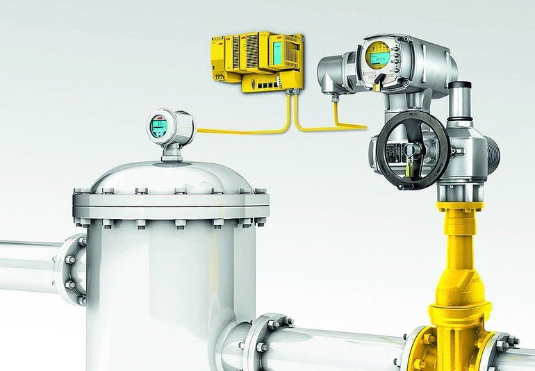
Safety instrumented systems are designed to detect dangerous process states automatically as they develop, then initiate appropriate countermeasures (also automatically). To fulfil this role, a SIS always consists of at least one sensor, one logic device and one final element – the actor that performs the corrective action. The final element could be an electric actuator connected to a valve, for instance. Three main criteria have to be satisfied to make sure the SIS conforms to the specified SIL:
- Systematic capability
- Maximum allowed probability of dangerous failure on demand (PFD)
- Architectural constraints
IEC 61508 and IEC 61511 are the international standards which define the criteria the overall SIS must comply with. By implication, the individual components of the SIS must also meet certain criteria, as explained in the following.
Systematic capability
IEC 61508 defines two alternative methods to ensure that a component is suitable for use in a SIS with a particular SIL rating. The first method (route 1S) requires everyone working with the system to follow certain procedures during its development, manufacture, maintenance and so on. The aim is to avoid systematic errors, for example due to miscalculations, incorrect specifications or design faults. This is the preferred route for newly developed components. The second method (route 2S) relies on evaluating field data to show that the components are proven in use and thus provide the required reliability. This method is mainly employed for components where comprehensive field experience exists. Sometimes these routes are supplemented with field tests at the end user’s site (see, for example, Namur recommendation NE 130). When choosing the components for a SIS, it is important to ensure that the systematic capability (SC) of each component matches the target SIL of the overall SIS.
Probability of failure on demand
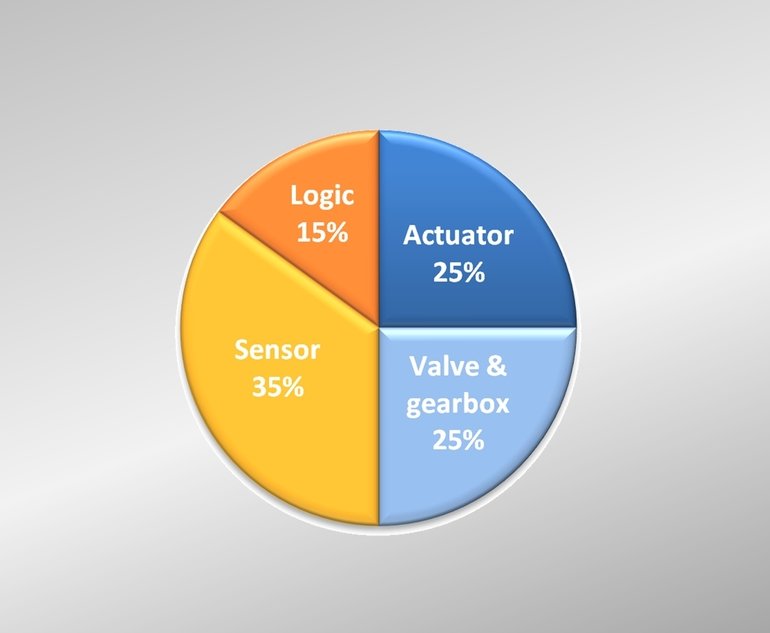
The probability of failure on demand (PFD) is the probability that the SIS will fail to perform its safety function when required. The relevant standards always state a maximum allowed PFD for the overall SIS. Since the SIS invariably contains at least one sensor, one logic device and one final element, none of these components must have a failure rate equal or close to the allowed maximum PFD of the target SIL. If they did, this would imply that the other components do not have any probability of failure – which is unrealistic. The standard does not specify maximum PFDs for the individual components, since they may vary with the system setup. Nevertheless, a PFD distribution of 15 % logic device, 35 % sensor, 25 % actuator and 25 % valve has proven to be a good guideline. According to this breakdown, an actuator for a SIL 2 SIS, for instance, should have a PFD of approximately ≤2.5 x 10⁻³.
Robust system architecture
The system architecture should aim to create a setup that is as robust and failure-tolerant as possible. Again, there are two general approaches. The first method (route 1H in IEC 61508) relies on a combination of sufficient redundancy in the system setup and a minimum safe failure fraction (SFF). The SFF is the fraction of system failures that are either detectable or lead to a safe condition. The second method (route 2H) is based on a combination of sufficient redundancy in the system setup and extensive field experience with the components used.
The architectural requirements have to be fulfilled at subsystem level. When choosing components for a subsystem of a SIS, note that route 2H may only be applied if each of the elements used in this subsystem meets the requirements. If this is not the case, the designer must follow route 1H and each subsystem must achieve the relevant minimum SFF. For a subsystem of a SIL 2 safety system that has no redundancy and uses complex electronic components, for example a microprocessor, this would result in a minimum required SFF of 90 %.
It is not necessary for all the components used in this subsystem to have an SFF of 90 %. For instance, it would be permissible to choose a component with an SFF of only 85 % as long as the overall SFF of the subsystem is 90 % or higher. Nevertheless, the system designer should be aware that using components that do not fulfil the minimum requirement implies that other components of the same subsystem must exceed this requirement. If route 1H is selected, it is therefore advisable to opt for components that fulfil the minimum SFF requirements for the target SIL. SIL certificates for components should be examined carefully in this respect, as they do not always take account of this recommendation regarding the SFF.
Special requirements and concerns for actuators
Field components such as sensors, actuators and valves are exposed to influences that logic devices do not normally have to withstand. These include environmental conditions such as temperature, pressure, humidity, contamination and vibration. Additionally, some of the field components may be exposed to abrasive or corrosive process media. When designing a SIS, it is of utmost importance to choose components that are able to withstand these conditions over the whole intended lifetime of the SIS. This is actually more important than the SIL capability stated in the component certificate, since a component will fail if it does not resist the environmental and process conditions it encounters. If a component fails due to such “out of specification” use, the complete SIS will not even fulfil SIL 1. The use of robust and comprehensively tested products is vital. Auma sets the standard with regard to electric actuators for these applications: apart from the SIL certification as such, the wide service temperature range between -60 and +60 °C is a basic requirement for deploying actuators successfully in safety instrumented systems, as is the robust and sophisticated design paired with very good corrosion protection. A few other technical questions always have to be clarified before an actuator is selected for a SIS. The discussion below makes no claims to completeness, but experience shows that these points are sometimes forgotten – resulting in major design faults in the SIS.
Other technical questions
The most important thing to clarify is the safety function to be executed by the actuator. It is additionally necessary to decide whether the actuator must perform only one or several safety functions, perhaps belonging to different safety instrumented functions (SIF). If the same actuator has to perform different safety functions (e. g. safe close and safe stop functions), it is essential to make sure that the priority of these functions matches the requirements of the system. The next step is to take a closer look at the detailed requirements of the SIF. For an emergency shutdown (ESD) function (typically safe open or safe close), it is crucial to specify the seating criteria in end positions. These may or may not be the same as for standard operation.
Among the other criteria that need to be considered are thermal motor protection and overload protection. In standard operation, these are valuable functions that protect both the actuator and the valve from damage. In the context of a safety function, however, it can be desirable for the actuator to override these two protective features. On the other hand, there may be circumstances in which these features are mandatory for the SIF as well. The most obvious example is thermal motor protection in conjunction with explosion-proof equipment. Here, overriding the thermal protection could lead to high surface temperatures that cause an explosion.
It is therefore imperative to consider for each individual SIS whether or not a particular protective feature is wished for. The protective functions of Auma actuators can be adapted to the requirements of the safety instrumented system. For valve actuation, the safe stop function is usually easier to define but if other final elements are involved, it may also be necessary to define precisely what is meant by a safe stop. Some questions need to be clarified when using the safe stop function during valve actuation, though, such as how much overrun is acceptable and whether self-locking of the actuator is needed. Not all actuators that offer a safe stop function also provide self-locking. In these cases, additional measures have to be taken to ensure that the safety system not only stops the actuator motor when requested but also maintains the valve in the required position afterwards.
Process control system separated from the SIS
Generally speaking, a SIS should be physically completely separate from the basic process control system (BPCS). As far as sensors and logic components are concerned, a SIS is almost always implemented in this way. Nevertheless, for the final element – the actuator and valve – this approach is often labour-intensive and costly, since two actuators and valves have to be purchased, commissioned and maintained instead of just one of each. There is therefore a tendency to use the same valve and actuator for both process control and the SIS where possible. Yet is this actually allowed? And if so, under which conditions?
IEC 61511–1 11.2.2, 11.2.4 and 11.2.10 state that the use of a single valve and actuator is permitted in principle but that certain, rather restrictive conditions apply. The most important of these are as follows:
- All components jointly used by the SIS and the BPCS have to be treated as part of the safety system, which means that – amongst other things – they have to comply with IEC 61508.
- The failure of a component which is used as part of both the SIS and the BPCS must not cause a failure of the BPCS that, in turn, could result in a request for the SIS safety function.
- The SIS and the BPCS have to be sufficiently separate to make sure that a failure in the BPCS has no negative impact on the SIS.
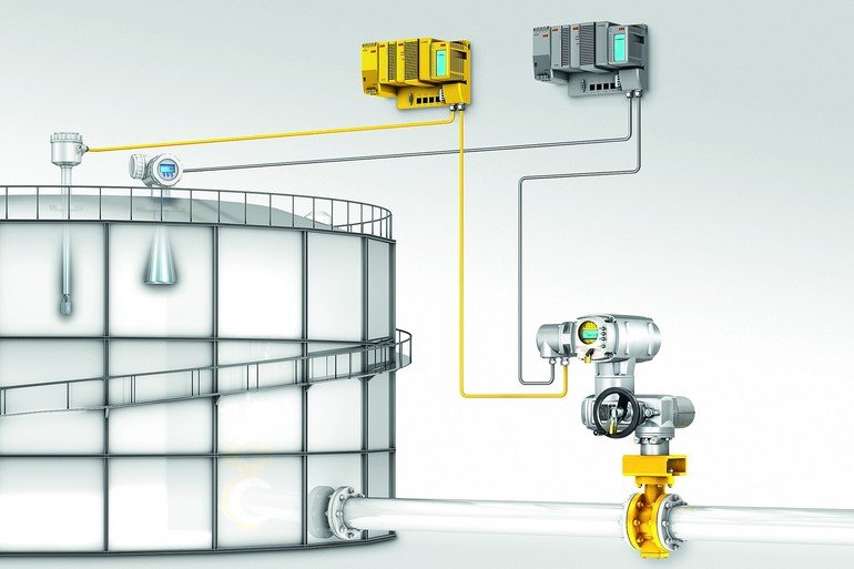
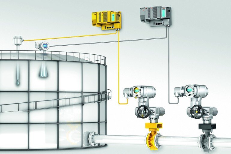
The first point should be more or less self-evident. The second is probably best described by an example: consider a tank with an inlet and assume that a SIS has to be implemented to prevent that tank from being overfilled. If the valve at the inlet is the only instance of the BPCS that stops the tank from being filled, because there is always enough pressure in the pipeline to fill the tank when the valve is open, then IEC 61511 does not allow the same valve to be used in the SIS. The reason is that a failure of this valve, as part of the BPCS, would require action by the SIS while simultaneously causing a failure of the SIS.
The third point is of particular interest for actuator controls, because it is here that the signals of the BPCS and the SIS come together. Hence, it is of utmost importance to ensure that a failure of the BPCS does not compromise any SIS functions. In particular, this means that:
- Signals from the SIS must always take priority over signals from the BPCS
- All BPCS wiring must be isolated from the actuator controls, so that, for example, overvoltage produced by a BPCS failure does not destroy the actuator electronics
- For the same reason, all inputs and outputs used by the BPCS must be isolated from all inputs and outputs used by the SIS
The last point, in particular, is often forgotten. If it cannot be fulfilled, then at least some parts of the BPCS have to be treated as part of the SIS.
Online search: cppPC117auma
Short facts : Electric actuators
Auma offers a comprehensive portfolio of electric actuators for various SIL requirements. For example, SA .2 and SAEx .2 multi-turn actuators as well as SQ .2 and SQEx .2 part-turn actuators with AC .2 or ACExC .2 actuator controls in a SIL version are TÜV certified and approved for the highest safety requirements up to SIL 2 / SIL 3 (SIL 3 for redundant system architecture). These products meet the increased requirements of the current second edition of IEC 61508. Auma has developed a particularly safe SIL module for AC / ACExC .2 SIL actuator controls which executes the safety functions. The actuators excel with the different seating criteria which can be defined for executing the safety function, including forced limit or forced torque seating in the end position. The mechanical load acting on the valve can thus be minimised.
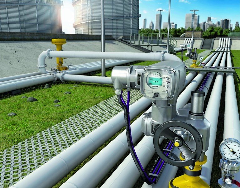
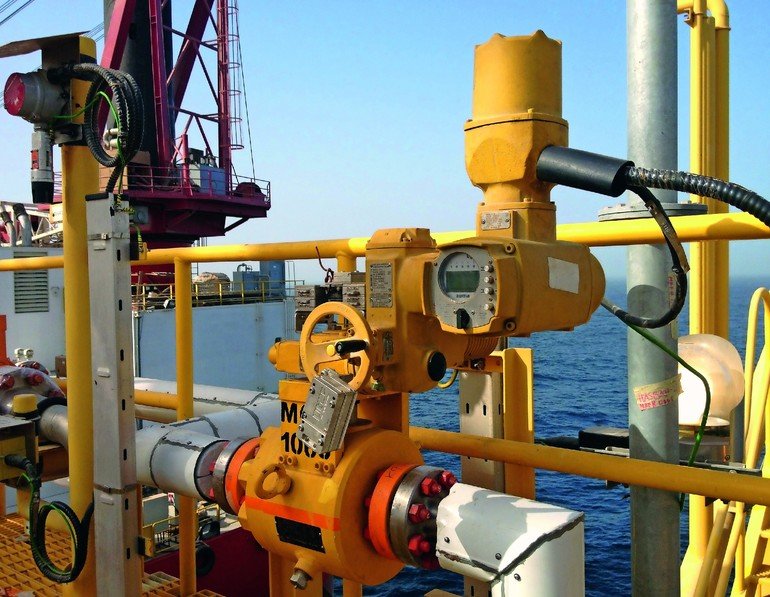 Auma provides electric actuators to support safety instrumented systems up to SIL 3
Picture: Auma
Author : Heike Schmeding
Technical writer,
Auma Riester


