Optimum connection of process I/O in explosion-protected areas is a decisive factor, not only with respect to safety, but also from an economic standpoint. Distributed remote I/O and fieldbus solutions can result in significant cost savings over conventional wired I/O in the areas of installation, instrumentation, wiring, engineering, operation, and maintenance.
The Author: Thomas Bartsch Marketing Manager, Industrial Automation Systems, Siemens
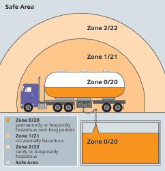
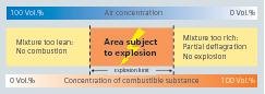
Explosive atmospheres can be caused by flammable gases, mists or vapours or by combustible dusts. If there is enough of the substance, mixed with air, then all it needs is a source of ignition to cause an explosion. In addition to chemical and petrochemical plants, mills, such as in the cement industry, are particularly at risk. The number of production areas which can be classified as potentially explosive rises with increasing product volumes. In areas where there is a risk of gas or dust explosions, strict regulations apply to equipment and facilities. These regulations cover and differentiate between different explosion protection measures as an explosion can only occur when the following factors are present:
- Combustible substance in the relevant distribution and concentration
- Oxygen
- Ignition source with sufficient energy
Primary explosion protection aims to prevent or restrict potentially explosive atmospheres. This includes avoiding the use of combustible substances, limiting concentrations, and inerting – that is, conversion to inert substances, for example using nitrogen or carbon dioxide. If the risk of explosion cannot be completely eliminated in this way, secondary explosion protection, with the aim of preventing effective ignition sources, is required. Tertiary explosion protection comprises measures to limit the effects of an explosion to a negligible level. These include explosion-proof or flame-proof designs and pressure release.
Explosion protection in automation
Within the framework of explosion protection measures, automation systems can offer various benefits: On the one hand, they can be used to maintain the concentration of combustible substances outside the explosive limits (measuring systems, gas warning units, etc.). On the other hand, automation components can be designed to ensure they do not act as sources of ignition in the context of secondary explosion protection.
Depending on the zone in which a device is to be used, it must belong to a specific device group and category with corresponding certification and must have the type of protection certified by an approved testing authority.
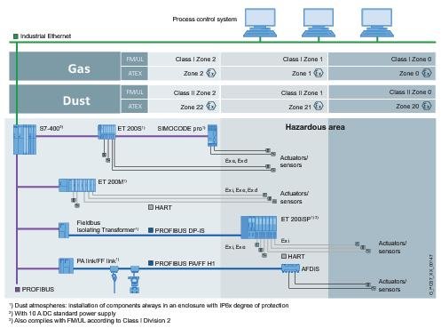
Whereas higher power equipment such as switchgear, transformers, control cabinets, etc. typically use „Flameproof enclosure“ or „Increased safety“ types of protection, measuring and control circuits and the electrical connection of sensors and actuators in hazardous zones can have an „intrinsically safe“ design. This means that voltage and current in the electrical circuit can be reduced with the help of safety barriers to such an extent that the minimum ignition energy and ignition temperature of an explosive mixture cannot be reached. Spark discharge and excessive heat therefore do not occur either in the normal operating state or in the event of an error. Isolating stages and isolating transformers are used for the necessary restriction of the voltage and current between the intrinsically safe and non-intrinsically safe electrical circuits. Intrinsically safe electrical equipment is suitable for use directly in the hazardous area. Communication between the field devices located in the hazardous areas and the process control system can take place in various ways: by means of conventional technology (4…20 mA) in point-to-point wiring, using distributed I/O modules that may be positioned in different zones depending on their version, or via a bus system such as Profibus DP, Profibus PA or Foundation Fieldbus.
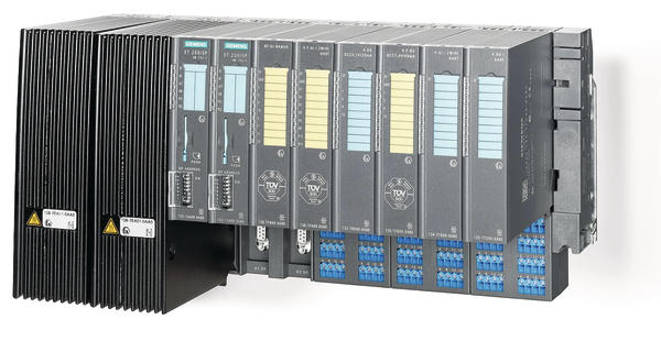
With remote I/O in hazardous zone 1
In conventional wiring, analog and digital I/O wires from the hazardous zone are combined into multi-core master cables via terminal boxes and connected to the I/O module, the automation system or the control system via marshalling racks and individually wired safety barriers and isolators. The overheads required for this can be reduced significantly by the use of intrinsically safe distributed I/O devices. For example, costs for branching boxes, distribution boxes, additional master cables and safety barriers are saved through the use of the Simatic ET200iSP distributed I/O system from Siemens, which can be installed directly in zone 1 of the hazardous area. Depending on the configuration, up to 256 digital or 128 analog field signals from hazardous zones 0, 1, 2, 20, 21 and 22 can be connected. Profibus DP is then used to transfer the data to the automation systems. Whilst some physical adaptation is necessary in order to use the fieldbus in hazardous areas the transfer protocol is identical in all operating environments. The use of Profibus DP is allowed up to hazardous zone 2 as standard. Using an isolating transformer and RS 485-iS transmission technology, Profibus DP can continue to be used as an intrinsically safe bus up to hazardous zone 1. The ET200iSP remote I/O stations have a modular structure and can thus be individually configured and flexibly expanded.
In addition to analog and digital I/O modules, the range of electronics modules also includes fail-safe modules. These fulfill high safety requirements in accordance with relevant norms such as IEC 61 508 up to SIL 3 and can be used directly without safety barriers up to hazardous zones 1/21. Connected intrinsically safe sensors and actuators can also be routed up to hazardous zone 0/20. This means that these fail-safe modules are suitable for applications such as ESD (emergency shutdown), vessel and boiler protection, and flame and gas appliances. Both standard and fail-safe data is transmitted via Profibus DP using the Profisafe profile. When used in the Simatic environment, the configuration of the I/O takes place via the Step 7 programming software, both in the standard and the fail-safe version. Pre-programmed blocks certified by the German Technical Inspectorate are available for fail-safe applications in the Step 7 optional packages Distributed Safety and S7 F-Systems. The connected Hart field devices can be configured and assigned parameters via the Simatic PDM Process Device Manager. By means of routing via Profibus DP, Simatic PDM allows direct access to the Hart field device data on ET200iSP. Installation costs can be reduced considerably with this remote I/O for hazardous areas and safety circuits. Potential for cost savings is opened up in the area of hardware thanks to the elimination of the need for safety barriers, the reduced wiring, the omission of master cables and the space-saving design. The uncomplicated parameter assignment, diagnostics down to the sensor/actuator level and the simplified safety evaluation provide additional advantages.
Fieldbus – even more possibilities
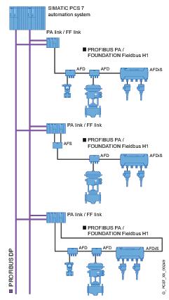
The use of Foundation Fieldbus or Profibus PA-capable field devices reduces the cable requirements even further. Using Profibus PA, it is possible to integrate field and process devices directly in hazardous zones 1, 2, 21 or 22; sensors/actuators can also be integrated in zone 0 or 20.
Profibus PA is the communication-compatible extension of Profibus DP which permits application directly in potentially explosive areas. By means of a two-wire line and intrinsically safe MBP (Manchester Coded; Bus Powered) transmission technology in accordance with IEC 61 158, it allows digital data transfer and energy supply. It is thus optimally suited to the direct integration of devices such as pneumatic actuators, solenoid valves, or measuring and analysis sensors in environments up to hazardous zone 0. Particularly in the USA, architectures with Foundation Fieldbus (FF Bus) can be found in many applications in chemical and process engineering. The protocols of the two bus systems are different, but both Profibus PA and FF Bus are based on the IEC 61 158 stand-ard, and the so-called Fisco (Fieldbus Intrinsically Safe Concept) model can be used on both.
The Fisco model provides important services for the practical use of FF Bus or Profibus PA in hazardous zones. According to this model, a network is intrinsically safe if the components involved do not violate defined limits for voltage, current, power, inductance and capaci-tance. In addition, the ex coupler, cables, field devices etc. which are used must be certified by an authorised approval authority, for example, the PTB (Physikalisch-Technische Bundesanstalt, German National Metrology Institute). As a result of this simplified model, costs can be saved in the planning and operation phase because a new safety approval is not required when devices are added or removed from the line.
Together with the active field distributors (AFD) developed by Siemens, Profibus PA and FF Bus become fault-tolerant fieldbus systems which can be used without restrictions. AFDs feature short-circuit-proof connections for the spur lines. Logic can be integrated to ensure automatic isolation of the faulty subsegments and bus termination in the event of a wire break or short-circuit.
In this way, Profibus PA networks, for example, can be modified safely, even during operation. Subsegments can be removed, replaced or extended without problems. AFDs also allow the switching of ring architectures with bus coupler and media redundancy, which makes a significant contribution to the availability of system components.
Moreover, the intrinsically safe version of the Simatic AFDiS active field distributor also permits fault-tolerant, intrinsically safe fieldbus installations. The integrated safety barrier of the AFDiS limits the energy in hazardous areas on the spur line to the intrinsically safe PA field devices and electrically isolates them from the main line. The AFDiS has relevant test certificates and can be installed in zones 1 and 2 or zones 21 and 22. It supplies up to six spur lines or five spur lines and a subsegment with a length of up to 500 m. The subsegment of an AFDiS with connected intrinsically safe devices extends to zone 0. An integrated fieldbus repeater is used with the Simatic AFDiS for even more robust fieldbus communication. The communication signals between the main line (trunk) and the spur line are regenerated in both directions, which achieves improved signal quality and freedom from feedback. Furthermore, all spur lines can be designed with the maximum permissible length of 120 m (60 m with Fisco), independent of the number of devices connected on the segment. The maximum permitted quantity framework of up to 32 nodes can also be fully utilised for intrinsically safe installations.
Hall 9, Booth 72
cpp-net.com/0112400
Share:


