The failure of signal circuits in instrumentation and control (I&C) systems due to transient overvoltages can cause a lot of damage. The availability of the plant or system can be increased – and the cost-effectiveness of plant operation therefore optimised – by using surge voltage protection devices. IEC 61643-21 and -22 are the decisive standards for surge voltage protection devices in instrumentation and control technology.
Silvester Paul
Transient surge voltages are generally the cause of unexpected equipment damage or plant failures in I&C technology. These voltages are caused by lightning strikes or switching operations in the supply system. Significant follow-on costs are incurred as a result of complex and time-consuming fault finding, purchasing new components, repairs and downtimes. According to IEC 61643-22, the surge voltage protection devices used to counteract transient surge voltages and limit them to an acceptable level for the equipment to be protected should comply with the requirements of IEC 61643-21 and the specifications relating to the protected system [1].
Surge voltage protection devices for I&C technology are selected according to criteria such as:
- Signal processing concept, e. g. two-, three-, four- or six-wire measuring technology
- Maximum signal voltage
- Surge voltage capacity
- Transmission frequency
The location of the surge voltage protection devices also plays a role. Protecting equipment in potentially explosive areas – for instance when intrinsically safe circuits are involved – necessitates compliance with specific requirements.
Flow or level measurements are typical applications for two-wire technology. Three or four-wire systems are preferred for temperature or weighing measurements. Temperature or level measurements in tanks frequently take place in Ex i zones. The connection system used and the space requirement must both be appropriate for the installation environment. Surge voltage protection devices for instrumentation and control technology are consequently available with different connection systems.
Applications and protection classes in I&C technology
IEC 61643-21 and/or IEC 61643-22 are decisive when testing and using surge voltage protection devices in telecommunication and signal cables. Additional recommendations, especially for protecting physical structures against electromagnetic lightning pulses, are listed in DIN EN 62305-3 and DIN EN 62305-4.
IEC 61643-22 (VDE 0845 Part 3-2) describes the principles for selecting, operating, installing and coordinating the surge voltage protection devices employed in telecommunication and signal processing networks [1]. IEC 61643-21 (VDE 0845 Part 3-1), on the other hand, defines testing procedures and performance requirements for surge voltage protection devices installed in the same environment [2].
An effective surge voltage protection system takes account of all cables that enter the building or the plant to be protected from the outside [1], [4]. Power supply cables must likewise be provided with surge voltage protection.
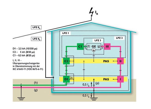
The standards mentioned above define a multi-stage surge voltage protection concept and classify the building into so-called lightning protection zones. A distinction is made here between outer and inner zones [4]. These describe how threats in the form of disturbance variables – such as lightning discharges and surge voltages – can be reduced using protection stages that are harmonised and coordinated with one another.
According to IEC 61643-22, the protection requirements must be taken into consideration wherever surge voltage protection devices are installed as part of protection measures. In this case, a cascaded arrangement of the devices at the zone interfaces offers significant advantages. An integral zone concept is especially relevant if an external lightning protection system is available. The first protection level at the entry to the building should thus correspond to requirement category D1. This protection must be capable of discharging a lighting current from 500 to 2500 A with a pulse shape of 10/350 µs. The input variable for the second protection level consequently has a significantly lower disturbance energy. This level must fulfil requirement category C2 with a discharge capacity of 1000 to 5000 A (pulse shape 8/20 µs). The third protection level is needed if the protection level is still not sufficient due to sensitive devices or because additional surge voltages could be coupled in between the second level and the device or equipment to be protected. The protection devices chosen for the third level must conform to requirement category C1, which specifies a discharge capacity of 250 to 500 A (pulse shape 8/20 µs). This cascaded arrangement accordingly reduces the disturbance energy to a value acceptable for the device to be protected. Depending on the installation conditions and the disturbance energy to be expected as a result of coupled surge voltages, a single surge protection device can be used to protect several protection zones in the same building.
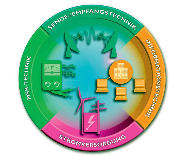
However, an effective protection concept does simply mean protecting the signals that occur in the instrumentation and control technology; it also includes the antenna, telecommunication and power supply cables. In addition, the voltage limiting properties of the surge voltage protection devices with regard to quadrature axis and common mode voltages must be harmonised and coordinated with the system’s protection requirements [1].
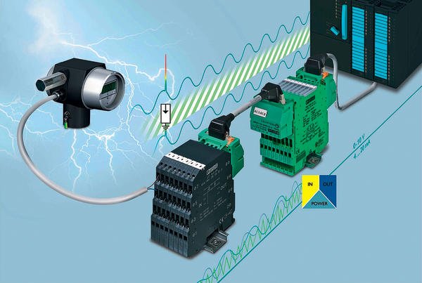
Surge voltage protection devices in measuring circuits
Surge voltage protection devices can be designed as single, two- or three-level arrangements in instrumentation and control technology. Suppressor diodes, varistors and gas discharge protectors are generally used as protection elements in this kind of environment. Many two-stage surge voltage protection devices have gas discharge protectors and suppressor diodes as protection elements. The suppressor diodes represent the fastest, but also the most sensitive, components of surge voltage protection devices in I&C technology. An ohmic resistance is frequently connected between the suppressor diode and the gas discharge protector to protect the I&C against high currents and decouple to the component with the higher capacity.
If surge voltage protection devices with decoupling elements are used in the measuring circuits, a check is required to determine whether it is permissible to increase the resistance. In the case of temperature measurements using two-wire technology, increased impedances in these circuits can be a cause of measuring errors. The maximum operating current of the surge voltage protection device should be taken into account, to ensure that the decoupling element is not destroyed by overheating as a result of the power loss.
The limit frequency fg is important in many applications, for example when bus systems are involved. It defines the behaviour of the surge voltage protection device as a function of the frequency. The capacitive and inductive properties of the components mean that signals are damped as the frequency increases. All metallic and conductive components must be incorporated in the equipotential bonding system at the transitions between the lightning protection zones.
Literatures
- 1. DINCLC/TS 61643-22:2007; Low-voltage surge protective devices – Part 22: Surge protective devices connected to telecommunications and signalling networks – selection and application principles
- 2. DIN EN 61643-21:2002; Low-voltage surge protective devices – Part 21: Surge protective devices connected to telecommunications and signalling networks – performance requirements and testing methods
- 3. EN 62305-3:2006; Protection against lightning – Part 3: Physical damage to structures and life hazard
- 4. EN 62305-4:2006; Protection against lightning – Part 4: Electrical and electronic systems within structures
- 5. Schimanski, J.; Überspannungsschutz [Surge voltage protection]. Theorie und Praxis [Theory and Practice]; Hüthig Verlag, 2002
Online-Info www.cpp-net.com/2210430
Share:


