Plant downtimes mean wasted money. In the last few years, therefore, strat-egies for availability based maintenance have been pursued and implemented in process and system engineering. This also includes measures for lightning and surge protection. The most appropriate maintenance strategy depends on the system to be protected, however. This is important in order to achieve a sensible balance between service and maintenance expenditure on the one hand and safety risks on the other.
Thomas Weiß
Lightning current and surge arresters protect systems and devices against interference as well as damage from surge voltages. Often, however, it is not the damage to the actual system electronics that is the cost causer, because the losses there generally only amount to a few per mille, or at most percent, of the investment. The main detriment is almost always due to the non-availability of the system concerned. An installation hit by partial lightning current can easily fail for several hours, if not days. Hardly any company can afford this. Modern systems of primary importance are usually already equipped with surge protection as a safeguard. In the case of secondary systems, the value at a given time tends to be compared to the necessary investment for adequate surge protection. Older system components frequently remain unprotected on the grounds that if overvoltage damage does occur, an up-to-date installation can finally be realised, ignoring the fact that if a thunderstorm happens at the weekend, staff could return to work on Monday morning only to find everything at a standstill and no longer functioning owing to a total system breakdown. They may subsequently be unable to process orders on time and, in the worst case, could face high claims for compensation. At any rate, the company’s good reputation or established business and customer relationships are likely to be at stake. Any firm affected in the past has had to learn the hard way that the availability of a system has a much higher price than its nominal value.
The use of suitable surge protection represents a crucial step forward. Transient surges are not only generated by lightning; far more are caused by switching operations and system perturbations. Electro-magnetic interference is also injected onto data lines for instrumentation and control, for example. This permanent interference is reliably discharged without any problems by the surge protection. Lightning energy, on the other hand, is considerably higher. This energy form is injected capacitively or inductively into all nearby conductors. Lightning current arresters (SPDs) can safely control this several times over. However, repeated lightning current or surge discharges beyond the specified range of the devices can overload the SPDs in an IT system. Arrester condition monitoring is necessary to ensure the protection and availability of the systems. SPDs for use in power engineering are equipped with an operating state indicator that enables the nominal operating state of an arrester to be recognised immediately. Unfortunately, this visual indication cannot be provided economically for arresters installed in IT systems. An alternative strategy has to be found.
Damage based maintenance
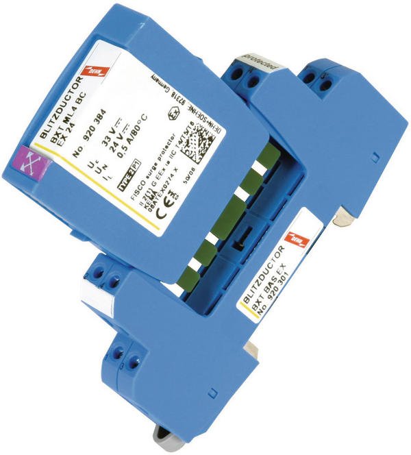
Arresters with fail-safe performance are mainly used for damage based maintenance. An arrester damaged by surges nor-mally generates a short-circuit on the signalling line. This means that further surges will also be short-circuited, usually without any negative effect. Of course, the signal on the line is short-circuited too and above all the system fails.
The arresters installed in a damage based maintenance system are pluggable. Each arrester consists of one discharge module, which carries out the discharge and is dam-aged if the above-mentioned situation occurs. A base part provides contact between the discharge module and the data lines. Significantly, this base part also is fitted with a make-before-break switch contact. If there is no arrester module, the switch contact connects the input side to the output side of the data line. Data transmission is thus possible even if no discharge module is plugged in. If the surge protection module fails as described above, its availability can be restored simply by removing the module from the base part. There is obviously no surge protection until the protection module is replaced, but the system is still available. The operator knows that a new arrester module must be plugged in to recover full protection. This damage based maintenance strategy is especially suitable for equipment and systems where short-time failures are unproblematic and the operator can afford to risk being without lightning and surge protection for a limited period of time.
Preventive maintenance
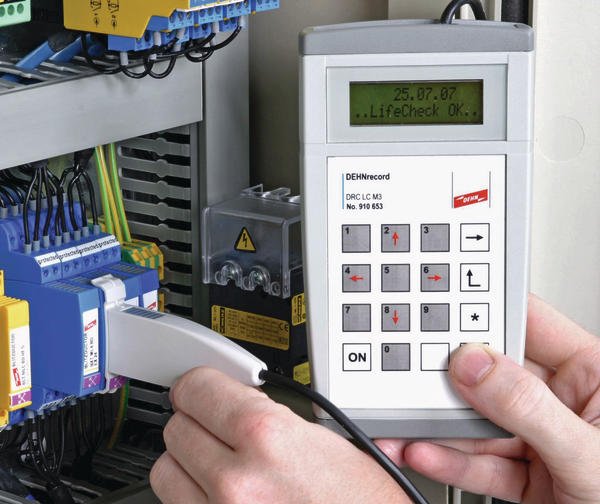
Preventive maintenance, by contrast, offers a higher degree of protection, though at a somewhat higher cost. EN 62305-3 requires maintenance and periodic tests to be carried out on a lightning protection system. Depending on the protection class, a visual inspection is stipulated at intervals of one to three years and a full test every two to six years. However, visually inspecting an IT arrester makes no sense because the devices do not usually indicate their own condition. Another procedure therefore has to be found. Measuring the arrester condition with suitable instruments – the traditional method – is very time-consuming, needs a lot of skills and is not generally very meaningful. For several years now, Lifecheck devices have allowed the arrester’s state to be determined using RFID technology. A transponder in the arrester monitors the protective circuit continuously for impermissible overload due to thermal overheating or electric impulse current. This information can be picked up with the corresponding hand-held reader with integrated RFID unit. The reader transmits power contactlessly to the transponder in the SPD, determines the status and shows it on the display (Arrester OK or Replace arrester). This test is quick and easy and can be performed within a few seconds without removing the SPD. Moreover, it can be conducted at any time without interrupting system operation because it does not interfere with signal transmission. Thermal or electrical overloading of all components is reliably detected before the arrester fails and the availability of the system to be protected is impaired. No special technical knowledge is required to undertake the test. The reader additionally simplifies the test documentation, which is described in EN 62305-3.
The test data (date, time, results) is saved and can be sent via a USB port to a PC for printing or saving. Preventive maintenance with Lifecheck thus improves protection and increases availability because overloaded components are detected before the protection device has a chance to fail.
Condition monitoring
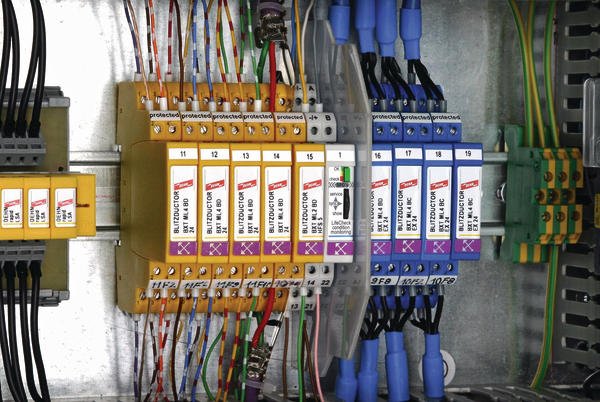
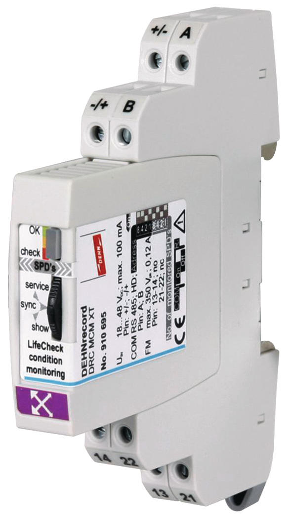
There are, however, some areas which require the greatest possible degree of system and equipment availability. In safety relevant technical facilities (nuclear or chemical plants, railway systems, aviation safety and security) as well as in other systems of high economic importance (production facilities), uninterrupted protection is indispensable. In this case, condition monitoring is the most suitable strategy. What used to be unthinkable is today a reality thanks to the RFID based Lifecheck technology. Instead of connecting the transponder to a hand-held reader, an RFID reader integrated in the switchgear cabinet is now sufficient. The Dehnrecord MCM XT is a rail-mountable device for simultaneous remote monitoring of up to ten BXT arresters (up to forty lines). Several condition monitoring modules can be interconnected for larger installations. The maximum configuration permits permanent monitoring of 150 BXT devices, equivalent to 300 twin wires. The visual indication means the status can be verified by glancing into the switchgear cabinet, or the fault indication can be transmitted to a higher-level control system via a floating, remote signalling contact. The detailed condition of all arresters can be displayed on any standard PC via a serial data port (RS 485) with the help of freely downloadable software. This information can also be transmitted via a gateway over Profibus or another bus system to the control room, where the necessary measures can be initiated. However, there is no need to panic if a fault signal is received. As described earlier, there is usually plenty of time until the overloaded arrester actually fails and the device can be replaced at the next opportunity to assure continuous protection and availability.
Hall 10.1, Booth K29
Online-Info www.cpp-net.com/2209454
Share:


