The risks of sparking caused by a direct lightning strike or discharge of conducted interference energies can be reduced to an acceptable level if the lightning protection zone concept is implemented at the planning and design stage of a chemical plant. The surge protective devices (SPD) must fulfil explosion protection regulations, coordination criteria and the requirements arising from the operating parameters of the measuring and control circuits.
The Author: Manfred Kienlein Senior Market Manager for the Process Industry, Dehn + Söhne
Special explosion protection measures must be taken in all industrial sectors where flammable substances form an explosive atmosphere with air. In 2003, Atex 137 (Directive 1999/92/EC) was transposed into several national laws. According to these regulations, the operator has a duty to provide an explosion protection document.
This document is based on a risk assessment regarding the potential hazards posed by the presence and expansion of potentially explosive atmospheres according to Ex zones. The possible ignition sources resulting from operating requirements are then identified and suitable equipment selected.
Lightning currents and overvoltages
When assessing the risk posed by potentially explosive atmospheres, account must be taken of the following lightning-related ignition sources according to EN 1127-1:
- Melting at the point of strike
- Heating of discharge paths
- Uncontrolled flashover if the separation distance is not maintained
- Induced voltages in cables and lines
- Lightning strikes into metallic lines that enter potentially explosive atmospheres
If lightning-related risks are determined (risk analysis according to IEC 62 305-2), all devices, protective systems and components in all categories must be protected by adequate lightning and surge protection measures. The IEC 60079-14 standard basically requires that the effects of lightning strikes are reduced to a safe level. In view of the fact that the Atex 137 directive calls for systems to be installed, mounted and operated according to the state of the art, EN 1127-1 and the new lightning protection standards (IEC 62 305 Parts 1 to 4) must be applied for explosion protection. Not only the effects of a direct lightning strike but also the electromagnetic effects of the lightning current on the electrical installation represent a risk in potentially explosive atmospheres.
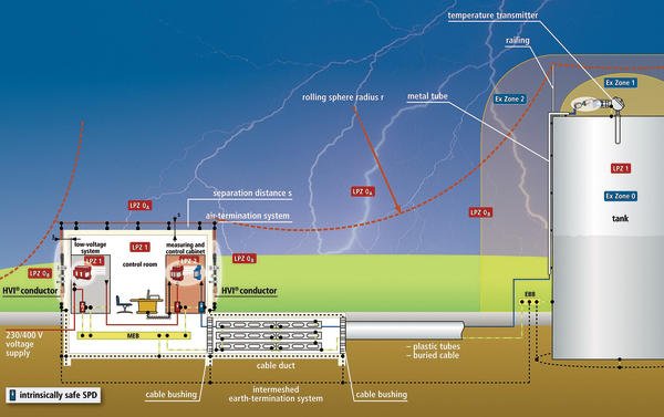
Figure 1 shows a typical installation of an intrinsically safe measuring circuit consisting of a combination of an isolating barrier, intrinsically safe measuring line and temperature transmitter (electrically isolated from the sensor). The following lightning hazards may destroy or interfere with the intrinsically safe measuring circuit (Figure 1) and create a risk of explosion for the system:
- Direct lightning strike into the lines of an intrinsically safe measuring circuit
- Lightning strike near the lines of an intrinsically safe measuring circuit
- Direct lightning strike into the air-termina-tion system of the measuring and control building
- Lightning strike near the measuring and control building
- Direct lightning strike into the tank
- Lightning strike near the tank
To provide protection against all lightning-related probabilities of damage to electrical equipment (in the control room and in the potentially explosive atmosphere), two surge protective devices (SPDs) must be integrated in the intrinsically safe circuit, namely one SPD to protect the isolating barrier in the control room and one to protect the transmitter on the tank. The SPD on the tank simultaneously prevents dangerous sparkover from the tank to the sensor line and affords additional protection against explosion.
Selection criteria for SPDs
Certain selection criteria must be fulfilled when selecting SPDs, like isolation from earth or the dielectric strength of the intrinsically safe equipment, device category and type of protection.
According to the IEC 60 079-25 standard, intrinsically safe circuits may be ‘isolated from earth’ or ‘connected to the equipotential bonding system at one point’ only. An intrinsically safe circuit is isolated from earth if it withstands a dielectric test according to IEC 60079-11 with at least 500 V to earth. If this is not the case, it can be assumed that the circuit is connected to earth.
SPDs that are approved for their intended purpose and fulfil the requirements of isolation from earth are the simplest option. These SPDs do not have to be disconnected from the intrinsically safe circuit during the dielectric test. The manufacturer of the intrinsically safe SPDs must prove that they are isolated from earth.
The entire intrinsically safe circuit has the ia type of protection. In our example, both SPDs must have this type of protection (see EC type examination certificate).
Since a sensor line entering zone 0 is connected to an SPD on the tank (Figure 1), the SPD must be additionally approved for this type of application. According to the EC type examination certificate, the SPD of type DPI MD EX 24 M 2 must have the following approval as a minimum: II2(1)G Ex ia IIC T4…T6.
Maximum permissible values
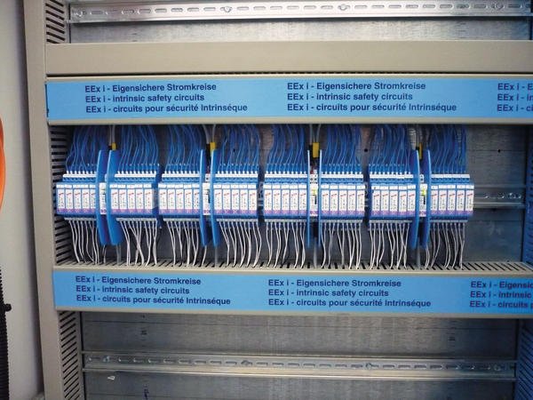
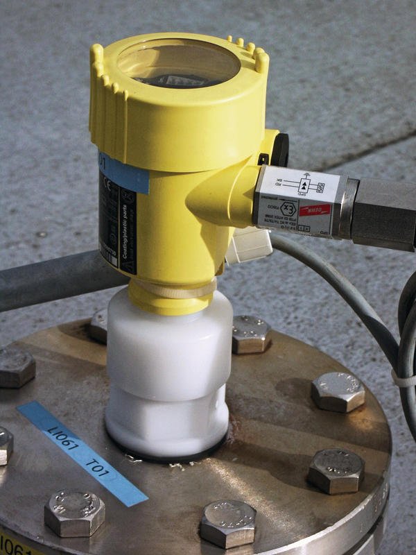
Before an intrinsically safe measuring circuit is put into operation, its intrinsic safety must be proven. The isolating barrier, transducer, cables and SPDs must fulfil the connection requirements. The EC type examination certificate confirms that the internal capacitances and inductances of the BXT ML4 BD EX 24 (Figure 2) and DPI MD EX 24 M 2 (Figure 3) surge protective devices from Dehn + Söhne are negligible and do not have to be considered when assessing the connection requirements.
According to its technical data concerning use in potentially explosive atmosphere, the intrinsically safe circuit to be protected has a maximum supply voltage Ui max (29.4 V(DC)) and a maximum short-circuit current Ii max (130 mA). The rated voltage Uc of the SPD must be higher than the maximum open-circuit voltage of the power supply system. The nominal current of the SPD must be at least as high as the maximum current Ii max of the isolating barrier to be expected in the event of a fault. The certificate becomes invalid if these boundary conditions are not observed when designing the SPD.
If the coordination requirements according to IEC 62305-4 and IEC 61643-21 are not fulfilled, the devices may be damaged even if SPDs are installed, putting the installation in a critical state. The safest solution is to use surge protective devices from a single manufacturer. In this case, not only the coordination requirement for the induced overvoltages (8/20 µs impulse) is particularly important but also a coordination test for lightning impulses (10/350 µs impulses). The SPD installed on the tank is located in lightning protection zone (LPZ) 0B and must therefore be capable of carrying partial lightning currents. The following additional requirements according to IEC 60079-14 must be fulfilled and proven, especially if an SPD is installed on the tank (lines from zone 0):
- Use of SPDs with a minimum discharge capacity of 10 impulses with 10 kA each without failure or interference with the protective effect.
- Installation of the SPDs in a shielded metallic enclosure and earthing via a copper conductor of at least 4 mm2.
- Installation of the lines between the SPD and the equipment in a metal tube earthed at both ends or use of shielded lines with a maximum length of 1 m.
In the application example described above (Figure 3) all these requirements are already fulfilled by using a surge arrester for field devices of type DPI MD EX 24 M 2.
Hall 11.1, Booth E15
cpp-net.com/0212467
Share:


