No matter how carefully a facility is planned and constructed, the risk of pressure surges cannot always be completely ruled out, particularly if the plant is modified or extended or the operating mode changes frequently. If the plant components are designed with sufficient stability, half the battle is won.
The author: Erhard Stork Developing Manager Department Valves and Controllers, ARI Armaturen
Very strong pressure pulses or surges, also referred to as water hammer, often occur in fluid-carrying pipes. The stresses on the pipes, valves and apparatus can be so high that the equipment concerned is damaged – or in extreme cases actually bursts. Before effective measures can be taken to combat this problem, it is important to analyse exactly which kind of water hammer is involved and what causes it.
If a globe valve (e.g. a butterfly valve) is closed abruptly while liquid is flowing through a pipe, the fluid flow immediately comes to a standstill and the kinetic energy is converted to pressure energy, in other words a water hammer pulse is produced upstream of the valve. This pulse is propagated at sound velocity from the point of origin against the original flow direction and reflected at points of discontinuity (vessels, pipe ends, etc.). The shock waves generally travel back and forth several times; they gradually lose their intensity due to dissipation before finally fading away.
If hot steam meets large accumulations of condensate because the piping system is insufficiently drained, sudden evaporation or flashing occurs. The resulting changes in volume are a cause of water hammer – in many cases violent – with strong pressure surges that can easily exceed the operating pressure.
Water hammer also occurs in condensate systems if subcooled condensate is fed into a condensate pipe that is partially filled with flash steam. A vacuum is created locally as the flash steam condenses. Strong pressure surges are likewise produced by the subsequent inflow of condensate at high velocity. In other words, there is always a risk of water hammer if condensate with different temperatures collects in a header.
Influence of water hammer on valves
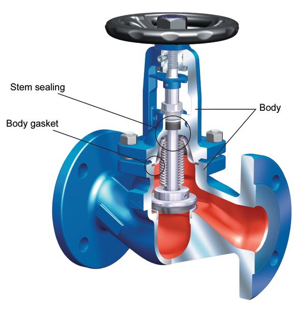
Taking the Faba-Plus globe valve as an example, Figure 1 shows the areas affected by pulsating pressure loads, which are also explained below.
The dimensions and design of the valve body are based on the pressure and temperature sizing parameters plus the safety margins laid down in the relevant regulations. As the water hammer values that occur in a plant can be far higher than the permissible values for the valves concerned, there is a risk that the body could break – at least with brittle materials that do not have a very high yield strength (e.g. cast iron).
The static sealing elements between the individual parts of the valve bodies are subjected to the same pressure and temperature loads as the body itself. If the maximum values for pressure and temperature stresses are exceeded here, the seals may develop leaks and fragments of them could even be blown out.
The seals for the stem guide are additionally exposed to dynamic stresses caused by the movement of the stem. Manual valves tend to be only rarely operated while control valves are in action regularly, if not continuously. The gland packing and the PTFE V-ring unit are the two classic systems. If this kind of seal is already badly worn, water hammer can easily result in leakage; gland packings have the advantage here that they can be retightened.
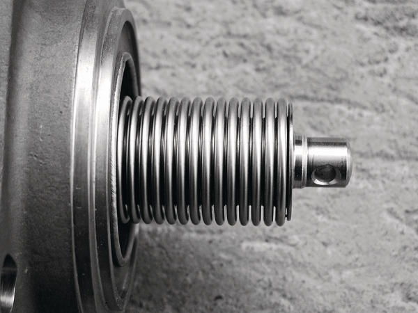
The stainless steel bellows seal provides a permanently leakproof and maintenance-free stem seal because wear is ruled out. The resistance to water hammer is consequently limited owing to the very thin walls.
Design measures
If water hammer cannot be completely prevented in the facility, a good starting point is to only use body materials that are sufficiently ductile.
It is a good idea to choose a grooved design in order to prevent gaskets from being damaged, or in the worst case blown out, due to water hammer. These seals generally consist of a shaped metal carrier and a soft seat. Once the seal has been installed and preloaded, the soft material, e.g. graphite or PTFE, is pressed into the carrier profile to give additional anchorage.
Chambered gaskets are another possible alternative between the top and bottom parts; the inner web shields the seal against the fluid. If water hammer occurs, it is prevented from even reaching the seal. The outer web provides support as well as extra protection against leakage. If the seal is faulty, no fluid jet can escape.
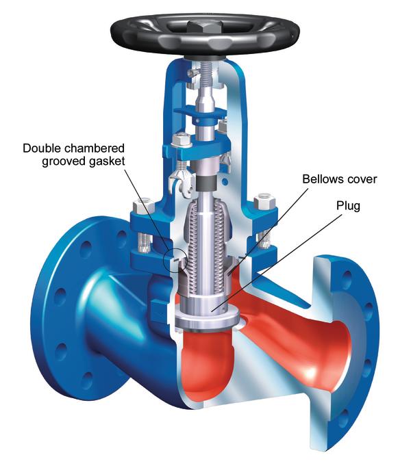
The resistance of bellows valves to water hammer can be further improved by shielding the bellows on the fluid side. The Faba-Supra i shown in Figure 2 is a typical example of this type of design. The protective rim welded to the top part also acts as a plug guide. Pressure surges or water hammer never even reach the bellows and no plug vibration is excited by high flow velocities.
Practical trials
Extensive trials were carried out at the Fraunhofer Umsicht Institute in Oberhausen (www.umsicht.fraunhofer.de) to determine the maximum loads as well as the effectiveness of the individual measures incorporated in the valve. The bellows globe valves were subjected to extreme stresses from water hammer.
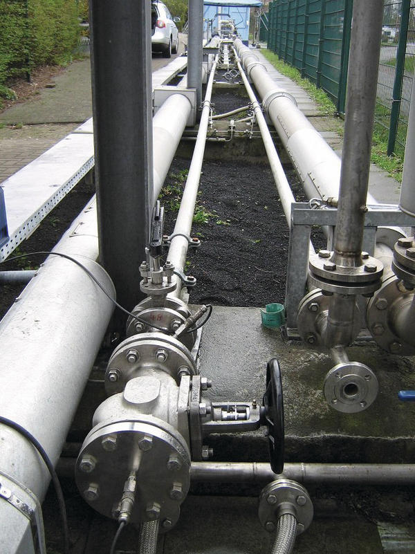
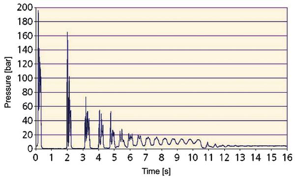
The Umsicht Institute owns an extensive testing facility on which hydraulic and cavitational water hammer can be produced under realistic conditions. The plant takes the form of a closed piping system in which water is pumped through a loop by a centrifugal pump. When a very fast-acting butterfly valve installed in the system is closed, the water column stops abruptly, resulting in water hammer at the inlet of the butterfly. These pressure peaks are propagated through the system; the water hammer pulse is reflected and replicated several times with decreasing intensity. By varying the velocity of the liquid flow to be braked, it is possible to obtain defined pressure peaks, which in this arrangement have a maximum value of about 200 bar.
Figure 3 shows the test valve at the end of a branch line; the measured pressure peaks are indicated in the graph (Figure 4).
The first tests were conducted on a standard Faba-Plus valve (DN 80 / PN 40) as shown in Figure 1. This valve is designed for a maximum pressure of 40 bar, yet there were still no negative values at 100 bar and no change to the bellows or the bonnet seal. The bonnet seal, which only has a single chamber with this valve, failed at around 130 bar and the first deformation of the bellows was observed at about 150 bar.
The same tests were then carried out on the Faba-Supra globe valve (DN 80 / PN 40), which is specially designed to withstand this kind of heavy load. This design was subjected to 200 bar water hammer pulses in a series of tests without any deformation or leakage being detected (Figure 5).
The additional shielding and integrated plug guide described above increase the resistance of this bellows valve, because water hammer no longer reaches the bellows.
Online-Info: www.cpp-net.com/0311430
Share:


