Check valves increase plant safety. When mixing liquids, for example, they prevent the liquid mixture from flowing back into the lines carrying the pure liquids, which would contaminate the pipelines and connected tanks.
Authors Marc Belzer Product Manager for solenoid valves, Samsomatic Monika Schneider Technical Documentation, Samson
Backflow prevention assemblies by Samsomatic are mainly composed of a differential pressure transmitter, inlet and outlet valves and a control unit. The differential pressure transmitter senses the pressure drop between the measuring points located immediately upstream of the inlet valve and immediately downstream of the outlet valve. Under normal conditions, the pressure upstream of the inlet valve is always greater than the pressure downstream of the outlet valve.
The differential pressure transmitter sends a standardised signal corresponding to this differential pressure to the control unit, where the signal is compared to a set minimum limit. If the measured differential pressure is below the set limit, the control unit simultaneously closes the inlet and outlet valves. Any medium backflow is thus prevented.
The Samsomatic backflow prevention assembly is suitable for use in safety instrumented systems (SIS). As a general rule, the required safety integrity level (SIL) is higher the higher the requirements placed on the safety instrumented system.
According to IEC 61511 ‘Functional safety – Safety instrumented systems for the process industry sector’, these requirements are described in three discrete levels (SIL1 to SIL3) and define the objectives to be achieved by the components used in an SIS. Based on calculations and depending on the version, the backflow prevention assembly can be employed in SIL2 or SIL3 applications.
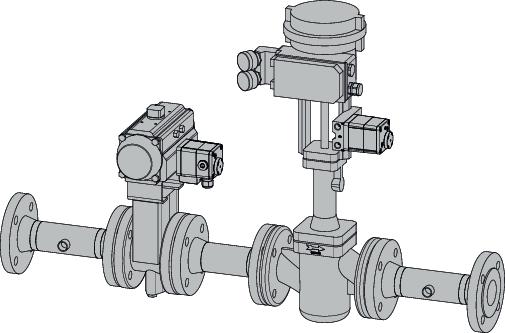
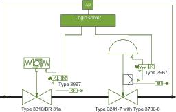
Possible architecture for SIL2 rating
A pneumatic ball valve with an external solen-oid valve is used as the inlet valve. A pneumatic control valve is installed at the outlet; it is fitted with an external solenoid valve and additionally equipped with a positioner for normal control operation. Alternatively, the external solenoid valve is not needed if the positioner comes with an integrated solenoid valve or if it includes a forced venting function, even if it is controlled using a two-wire connection. The logic solver supplies the solenoid valves of the inlet and outlet valves with control voltage (e. g. 24 V(DC)) as long as the differential pres-sure between the inlet and outlet valves is greater than the set limit. In the event of an emergency, i. e. if the differential pressure falls below the limit, the control unit interrupts the electric binary signal supplied to the solenoid valves. The solenoid valves then cause the fail-close action pneumatic actuators to vent. The inlet and outlet valves are closed.
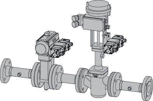
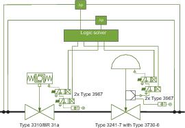
Possible architecture for SIL3 rating
The assembly for such applications also includes a pneumatic ball valve as the inlet valve and a pneumatic control valve as the outlet valve. In contrast to SIL2 applications, each of these two valves is fitted with two solenoid valves connected in series. In addition, both the differential pressure measurement and control are performed by redundant units. As a result, both the ball valve and the control valve are moved into their fail-safe positions by deenergising the associated solenoid valves if the limit is not reached in one of the redundant measurement and control channels. Moreover, the outlet valve is equipped with a smart positioner. A positioner with a partial stroke testing (PST) function reduces the probability of failure on demand.
During a partial stroke test, the valve is briefly moved into a predefined position before returning to its operating position. If performed at regular intervals, such partial stroke tests can indicate that the valve is jammed in its operating position and will not be able to move into its fail-safe position on demand.
To optimise the assembly, it is possible to mount an additional electronic limit switch (e. g. Samson Type 3738) on the on/off valve at the inlet, which can perform an automated stroke test similar to the positioner on the control valve.
According to IEC 61511, the safety instrumented functions should be separate from the non-safety instrumented functions wherever practicable. If a failure of the non-safety instrumented function does not impair the safety instrumented function, it is also possible to integrate a unit into the safety instrumented system as well as the control loop. This option is available for the outlet valve utilised in the Samsomatic backflow prevention assembly. The smart positioner allows the control valve to be used for control tasks. At the same time, the valve’s fail-safe action is maintained as the wiring of the solenoid valves takes priority over the positioner’s control function. This ensures that the actuator is vented on demand regardless of normal control operation, forcing the control valve to move into its fail-safe position.
Using the control valve simultaneously in the control loop and the safety instrumented system provides an added benefit in terms of safety monitoring: the control function allows plausibility checks to be performed easily, for example by monitoring the setpoint deviation. Constant availability monitoring is also pos-sible because the valve needs to move into different positions depending on the process requirements.
The Samsomatic backflow prevention assembly is designed for universal use. The inlet and outlet valves are taken from the wide Samson product range, which allows them to be tailored to specific conditions. For example, valve bodies in different styles and made of different materials can be selected to match the process medium and ambient conditions.
cpp-net.com/0115431
Share:


