Spurred by the pharmaceutical industry’s demand for continuous, low-rate powder feeders, where an hour’s worth of material might be as small as a teaspoon of sugar and accuracy is measured in milligrams, the development of precision microfeeding technology today opens up new avenues of operation and efficiency improvements for processors in a variety of industries. To realise its full promise, however, microfeeding requires that especially rigorous attention is paid to every aspect of feeder design and application.
Jim Foley
Accurately and reliably controlling the flow of material at normal process rates can be challenging on its own. Add the need to control the flow of some minor ingredients in the process in micro-regions as low as 20 g/h. Further compound the problem by requiring a level of precision that permits only a scant few percent sample-to-sample variation. This is the challenge of microfeeding. The development of microfeeding technology emerged primarily as a result of the recent decade’s shift towards Process Automation Technology (PAT) as sanctioned by the FDA. This initiative has hastened the application of continuous processing techniques in the pharmaceutical industry. Moving to a continuous process necessitates the elimination of manual feeding of minor ingredients and creates a real need for microfeeding technology.
Testing the limits
Unlike continuous, higher-rate feeding, microfeeding tests the limits of measurement and control and requires scrupulous attention be paid to every aspect of design and execution. As will be seen throughout this discussion, a single reality governs the challenge of continuous microfeeding: in microfeeding, every detail matters.
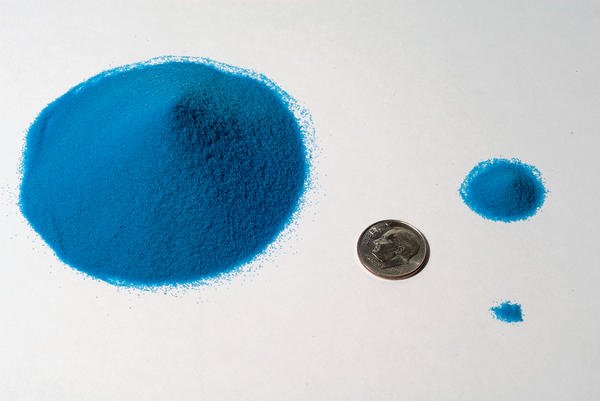
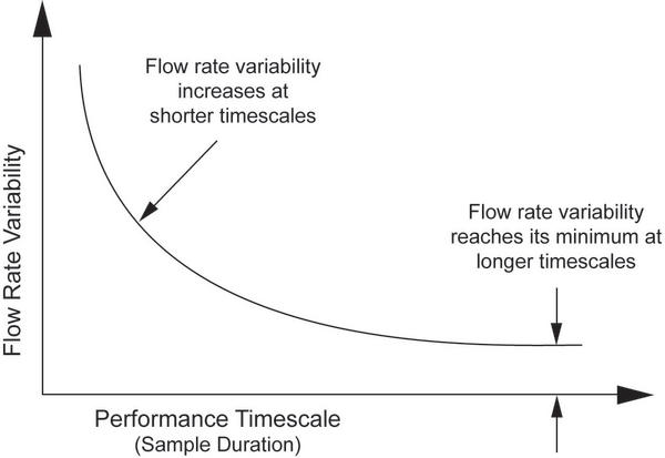
For the purposes described here, microfeeding can be defined as controlling the flow of a powdered or other small particle-size material at a range of feed rates from 2000 g/h down to 20 g/h or lower. At 20 g/h, this translates to 0.33 g/min or just 5.5 mg/s. Expressing this limit in terms of a second-to-second flow rate is intended to highlight the need to first consider the question of performance timescale, the time over which the allowable variability of flow rate is to be specified. The graph illustrates the typical relationship between flow rate variability and performance timescale. Both these parameters are dictated by process and product quality requirements: flow rate variability is commonly reflected in the familiar feeder accuracy repeatability statistic. Performance timescale is the time basis for its sample based measurement (i.e. sample duration). Here it can be seen that flow rate variability achieves its minimum value – a value that characterises the feeder’s ongoing performance level – at longer performance timescales (sample durations). On the other hand, at shorter and shorter performance timescales, the measured sample-to-sample variability increases. This relationship is universal in feeding and is also expected for several reasons. Firstly, at a given feed rate, as sample duration decreases, sample weight decreases in proportion. Even if it were pos-sible or practical to obtain physical second-to-second samples of a discharge stream, at some point – as sample duration and weight diminish –, the ability to confidently resolve these sample weights becomes compromised, depriving the feeder control system of the weight measurement integrity it needs to make useful control corrections. Measurement errors actually affect both the feeder’s ability to control and the sampling system’s ability to provide a reliable measurement of accuracy. Also, as sample times get shorter, the inherent timing errors of the sampling system and the control system have a larger impact.
Secondly, even if a near-instantaneous sample could be taken and its weight measured with sufficient precision, the control scheme of any gravimetric feeder could not, and should not, act on such a minimal and transient basis, to prevent it responding too slowly or, worse, acting on false ambient effects or other sources of measurement error. By design, gravimetric feeder weighing and control systems that are suitable for use in microfeeding must be able to effectively identify and extract legitimate dynamic weight data in a process environment where the signal-to-noise ratio climbs ever steeper as the measurement timescale is reduced.
Thirdly, apart from the more theoretical reasons outlined above, a real-world assortment of physical and mechanical factors affect flow rate variability at short timescales but tend to average out in longer samples. Material properties such as particle size, cohesiveness and through-the-feeder handling characteristics like screw fill uniformity and behaviour at discharge have an especially strong impact on feed rate variability over short timescales. Factors common in the processing environment such as vibration, air currents, or other disturbances also act to reduce achievable feeding accuracies in short-timescale applications (and especially in microfeeding where rates are so low). Finally, aspects relating to the feeder itself, such as screw pulsing, achievable weighing resolution, the type and quality of its signal processing, and the frequency of control updates among other factors, all combine to contribute to the overall variability-versus-timescale picture. In contrast to most higher-rate applications where the primary focus of concern is on the feeder’s ongoing level of performance (reflected by typical catch sample durations of about 60 s), many microfeeding applications require that feeder performance be gauged based on performance timescales somewhat shorter than a minute. Thus, the factors presented above have special relevance for microfeeding applications where both sample size and duration are miniscule.
Considering the few manufacturers who even offer such a capability and the range of potential microfeeding applications industry-wide, it is not appropriate to state specific values for feeder repeatability nor is it advisable to state a specific measurement timescale. In fact, as a starting point, these values are dictated not by the capabilities of any available microfeeding equipment but by the desired quality, properties and attributes of the end product being produced, as reflected by its composition and the degree of permissible ingredient variation. Only then, and by working backwards from these product/quality based standards, can feeder performance requirements be reasonably specified.
Microfeeder types
Understandably, a material’s physical and handling characteristics strongly affect the consistency at which it can be fed, or whether it can even be fed at all at these very low rates. Particle size, cohesiveness and other properties combine to determine a specific material’s potential for successful microfeeding. Thus, the first step in considering microfeeding is to evaluate the material itself. This should involve close consultation with the feeder manufacturer and will often require laboratory testing.
The vast majority of low-rate and microfeeding applications employ the loss-in-weight principle of operation in which the feeding unit, supply hopper and material are isolated and continually weighed. The discharge rate is then controlled to achieve the desired loss in system weight per unit time. The types of metering device capable of feeding at low rates include the screw, cone, vibratory tray and disc varieties. When applied at very low rates, this form of metering device typically employs twin screws, located at the bottom of the feeder’s supply bin to capture and transport the material to be discharged. The uniformity with which the material fills the screws’ advancing cavities influences the achievable degree of feed rate control. The advantages of this approach include good linearity, a partial positive-displacement action provided by the advancing cavities, good self-cleaning characteristics and anti-flooding design. Maximum particle size limitations and the possibility of discharge pulsing at low screw speeds are among the disadvantages.
The cone type involves a hollow cone, positioned horizontally and partially filled with material. As the cone is slowly rotated, the material adopts its natural angle of repose within the cone and cascades from its smaller open end to discharge. Cone feeding is primarily used for free-flowing pelletised or granular materials displaying consistent cascading behaviour. It is generally not employed with powdered materials.
Mainly appropriate for powders and other small particle-sized materials, disc feeding features a round plate with a circumferential channel or groove cut near its edge or small discrete pockets. The grooved disc is positioned off-centre at the bottom of the feeder’s bin, so that the grooved region emerges from beneath the bin during a portion of its rotation. In the bin, material fills the channel and is sheared as the rotating groove emerges. Once outside, a diverter extracts the material and moves it off the disc’s edge to discharge. Whereas the rotation speed can be closely controlled and the metering groove geometry engineered to the application, concerns relating to the uniformity of channel fill and the consistency of the subsequent shearing action prior to material diversion require special attention when feeding powders that are cohesive, have a tendency to clump, or otherwise hesitate to occupy a small void.
Anatomy of a microfeeder
Detailing the design considerations for microfeeding is best approached by addressing its three main elements: weighing, control and metering systems. Achieving precise feed rate control begins with accurate weight measurement. In very low-rate, loss-in-weight feeding, where the total feeder system weight declines at a low rate and the measurement environment is frequently far from ideal, the challenge is to obtain legitimate, useable weight measurements in the shortest possible time. To accomplish this demanding task, the first and most basic requirement is for reliably high weighing resolution. High resolution is needed to precisely discern the small differences in system weight that characterise low-rate feeding and permit more frequent corrective adjustments to the metering rate, enhancing moment-to-moment feeder performance. Over the last few decades, developments and refinements in digital process weighing technology have made continuous on-line microfeeding possible. Up to six weighments per second at resolutions of up to 1:4,000,000 are now possible, theo-retically enabling the detection of a change in feeder-system weight in the order of one milligram. However, considering the application-dependent issues of feeder performance, timescale requirements and the imperfect environment in which the feeder is likely to operate, basing a corrective control action on such a small-scale measurement is neither prudent nor required. A more feasible approach is to first isolate the feeding system as much as possible from the influences of its environment.
The possible agents of measurement contamination include shock, vibration and other perturbations such as draughts, and even convective air currents. Thus, microfeeders are often installed on carefully engineered and tuned mass plates with additional shock/vibration isolators. Draught shields enclose the feeder to protect against airborne forces. Especially flexible inlet and discharge connections are used as required in sealed systems. Even the selection and routing of cabling cannot be overlooked as a source of unwanted force transmission. Finally, weighing systems that exhibit any significant deflection are inappropriate for use in microfeeding. The meticulous measures taken to physically isolate the feeder comprise the first line of defence against environmental contamination. A formidable second line is taken up by sophisticated post-measurement filtering and processing techniques geared to extract meaningful weight data from the raw measurement signal.
For a loss-in-weight feeder to compute its actual discharge rate, it must compare that value to the desired rate (setpoint), calculate any required corrective motor speed adjustment and accurately determine the change in system weight between two discrete operating intervals. The controller’s self-tuning software sets the interval time and the weight filter automatically, based on the setpoint. It also measures the weigh noise, compares it to the setpoint and adjusts the weight filter and the control parameters accordingly.
Also of concern in the area of control are the issues of refill and perturbations. During refill, whether manually or automatically performed, the essential basis for loss-in-weight control – measurement of the system weight – is unavailable. Where refill is performed quickly, the system senses the abrupt increase in system weight and simply regards the event as a perturbation. Its response is to hold the metering speed constant at its most recent, pre-disturbance value and maintain it there for at least the settling time of the weigh filter, or until it once again senses the return of the expected decline in system weight, at which time it will automatically revert to gravimetric operation. To improve the refill response time, the self-tuning increases the weight filtering speed during and after refill. At the moment when it switches over to gravimetric operation, it dynamically lowers the weight filtering speed again. In a fully automated system a constant, metered refill is preferred to avoid unnecessary perturbation. A refill device such as a volumetric feeder can be used. Where refill is performed more slowly, some systems offer real-time automatic adjustment of the metering speed.
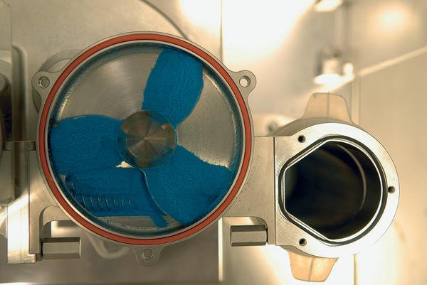
Mechanically, microfeeder metering system design involves much more than simply miniaturising a larger scale feeder. While microfeeders are physically small, material handling considerations are dominant. Designed to hold a relatively small supply of material, a loss-in-weight microfeeder’s integral hopper is typically a vertical cylinder or, even better, an inverted cone type (wider at its base) to promote continuous flow even with cohesive materials, which might otherwise exhibit a stick-slip action on the hopper wall. A slowly rotating vertical agitator prevents hang-up of less than fully free-flowing materials while a horizontal scraper, rotating directly above the screw trough or disc channel, helps assure a consistent fill of the metering element and near-complete emptying for cleaning.
This design feature is of particular interest to any industry feeding high-value minor ingredients, such as flavours or pharmaceutical active ingredients. For screw-type microfeeders, the solid, intermeshed, twin-screw approach is often most appropriate owing to the positive displacement-type effect afforded by its advancing cavity design. A low screw pitch enables finer control and smoother discharge by ena-bling screw speed to be maximised for a particular feed rate. To minimise any discharge pulsing due to screw rotation, the twin screws are set 90° out of phase and an appropriately sized screen mesh can be positioned at the end of the screws to further buffer the discharge.
Hall 7, Booth 366
cpp 401
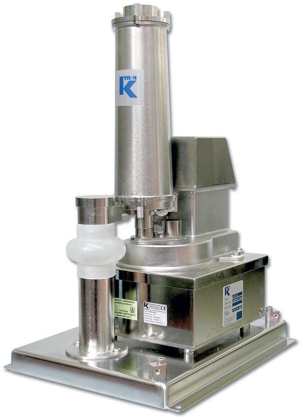
Further information about K-Tron’s feeding devices
Powtech 2008
Share:


