

Pressure is the second most frequently measured process variable in industrial processes, following temperature. Reliable pressure measurement of liquids, steam and gases is an important prerequisite for both the optimisation of procedures and the efficient use of energy and raw materials.
The author: Wolfgang Schuka Product Manager for Pressure Measurement, ABB Automation Products
Whenever liquids or gases are moved, stored or processed, values such as (gauge or absolute) pres-sure, differential pressure, level and flow must be measured precisely and reliably. Pressure measurement devices are therefore subject to high requirements. Steam is involved in different industrial applications, for example in the chemical and pharmaceutical industry, food industry for sterilisation, for heating, or to drive generator turbines in power plants. All these applications use steam boilers where filling levels have to be measured. Level metering is the basis for control and process control in many industries using process technology.
The amount of energy required to generate steam with a certain pressure in a closed vessel can be calculated from the enthalpy of water plus the vaporisation heat at the respective pressure. The enthalpy is the difference between boiler water temperature and boiling temperature, multiplied with the specific heat and density.
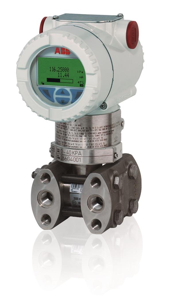
Since steam boilers are under pressure, differential pressure transmitters (e.g. ABB type 266MST) must be used for level measurement in order to compensate for the vessel’s overpressure.
To make sure during this differential pressure management that hot steam does not condensate at the colder offset side of the transmitter in an undefined way, leading to a changing water head, a condensate offset vessel is usually added to the measurement system.
Due to the condensate vessel, the water seal/water head on the offset side of the transmitter always has a constant level. This water seal also serves as a reliable temperature barrier which protects the transmitter against the high steam temperature. In the condensate vessel, the water vaporises and accumulates up to a defined, constant level. Excessive condensate will flow back to the vessel.
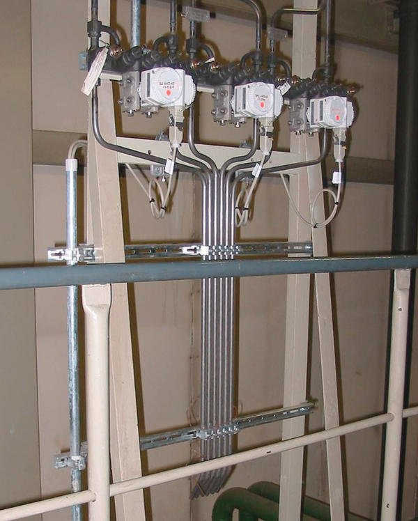
To make sure a transmitter can be de-installed for inspection without any problems, a triple valve block is installed directly before the transmitter for differential pressure measurement.
This allows the pressure, which may vary between the individual connecting pipes, to achieve identical pressure values through the counterbalance valve while the process is reliably shut off by means of the other two valves. At the same time, the transmitter can be removed from the measuring point without interrupting the process.
When measuring steam, a quintuple valve block combination, i. e. a triple valve block with two separate exhaust valves, is preferably connected in front of the transmitter. In contrast to a compact quintuple valve block, the sepa-ration of the exhaust valves prevents hot steam from getting in contact with the transmitter when exhausting the pipes, thus causing damage to the transmitter.
ABB pressure and differential pressure transmitters are used for standard applications as well as for demanding applications in automation environments, for monitoring and for safety-related measurements with SIL2 and SIL3 TÜV certification. Hart 4…20mA, Profibus PA, Foundation Fieldbus or Modbus communication are available. The measuring error of the transmitters is 0.025, 0.04, 0.06, 0.075 or 0.1 % of rate, depending on the requirement and type.
Measurement parameters can easily and individually be entered via buttons and LCD (optionally also using the TTG (through the glass) technology, without having to open the cover). It is also possible to correct or configure the zero point and span without any specified pressure. Examples for diagnostic functions are self test, limit value monitoring with event counter, drag indicator functions and simulation functions.
Level measurement in a vacuum
In order to measure the level in a vessel under vacuum, the entire measurement system must be able to operate under vacuum conditions. Suitable measurement systems include:
- Hydrostatic measurement with instilling into the condensate/offset vessel
- Hydrostatic measurement with instilling into a T-piece below the condensate vessel
- Hydrostatic measurement with a vacuum-tight pressure sensor
The measurement with instilling into the condensate/offset vessel is a proven, hydrostatic measurement system using a differential pressure transmitter. The measurement system is simple, but it relies on high mechanical requirements since the valves also have to be vacuum-tight. Furthermore, liquid has to instill into the condensate vessel since the required water column standing before the transmitter and in the condensate vessel vaporises due to the vacuum. This loss of water must be offset. However, the instilling of liquid directly into the condensate vessel causes unrest/pulsations as the instilled water abruptly vaporises. A permanent feed is therefore required to ensure correct measurements. Completely desalinated water must be available at the tapping point, the feed of which should be monitored. Otherwise the measurement value would slowly start to drift away if instilling should fail.
In contrast to the first hydrostatic measurement system, water is not instilled into the condensate vessel, but into the impulse pipe below the condensate vessel using a T-piece in case of the second type of hydrostatic measurement. This prevents the pulsation problems which occur when instilling directly. Otherwise, the other properties are identical to the first type of hydrostatic measurement.
Instrument isolators/pressure sensors
When measuring pressures and differential pressures in aggressive media, special isolating diaphragms/pressure sensors, with diaphragm material adapted to the media to be monitored, are used to protect the measurement cell. Integral capillary tubes filled with silicon oil are used for connection to the measurement cell of the differential pressure transmitter. Such pressure sensors can also be used to implement a stable, hydrostatic measurement system in the vacuum range. The benefit is that the complete mechanism and the monitoring of the previously described measurement systems are not required; on the other hand this assembly with increasing length involves increasing temperature dependence of the capillary tube between transmitter and pressure sensor. It is therefore recommended to make sure that no significant variations of environmental temperature can occur. Furthermore, the pressure sensors should be in a vacuum-resistant version. While this is not really a problem, this should not be forgotten. The amount of instrumentation required as such is comparably low. Only large flanges (standard: DN80/DN50) must be made available on the vessel side. To ensure a secure measurement especially for applications in- volving pressure sensors in the high vacuum range, the transmitter should always be installed on the level of the lower pressure sensor connecting port, or preferably below the lower connecting port. This is recommended to make sure that in case of a higher level mounting the vacuum generated by the oil filling in the capillary tube does not add up to the vacuum in the vessel, which may lead to the steam pressure of the oil filling being undercut. In this case, the oil would outgas, generating gas bubbles and causing the measurement to drift away.
All three hydrostatic measurements have a small disadvantage: they detect the pressure of the water column above the transmitter which with reference to the real level depends on the density of the medium.
This measurement error, inherent to the functional principle, is usually set off in the control system using correction modules.
Halle 11, Stand A35
Online-Info: www.cpp-net.com/2111402
Share:


