The components for temperature measuring points can nowadays be ordered quickly and conveniently with just a few mouse clicks. Working out their requirements in detail takes much longer. You have to find answers to question upon question.
- Would a mechanical temperature measuring instrument do the job better than an electrical one?
- What is the leading length in the measuring assembly, the insertion length of the thermowell in the process or the standardised sensor length of the thermometer?
- Are the dimensions of the pipe and the nozzle even compatible with these standard lengths?
- Is a wake frequency calculation stipulated for the thermowell and if so, what influence does it have on the design of the measuring point?
And on top of all this, there is a widespread conflict of interests: the person responsible for the instrumentation wants the thermometer to be immersed as deep as possible in the process in order to obtain meaningful results. At the same time, the plant safety officer insists that the smaller the insertion depth, the less likelihood there is of thermowell failure.
Designing temperature measuring points with a thermowell clearly involves a complex jungle of decisions. The following observations, based on five central aspects, can provide general guidance.
Positioning of the measuring point
The question of where the measuring point should be installed is easily answered: wherever there is no danger to, or due to, the thermometer and the process is not disrupted by the measurement. This undoubtedly applies to the straight section of a pipe, a sufficient distance from any elbows, valves or other measuring instruments. A distance of about eight or ten times the pipe’s inner diameter should normally be adhered to after an elbow, for example.
Many users position the measuring point directly in an elbow. However, this then leads to the next question, namely whether the thermowell should be installed facing upstream or downstream – and this time the answer is rather less straightforward. It all depends on which part of the world you happen to live in. Whereas the German VDI 3511–5 directive recommends installing it facing upstream, the Russian Gost 8.586.5 describes installation facing downstream. The American ASME PTC 19.3 TW-2016 standard, on the other hand, mentions both options without expressing a preference for either.
There are many processes where the temperature has to be monitored redundantly, in other words using several thermometers, for safety reasons. To avoid mutual interference, the measuring points must comply with certain minimum distances. These are specified in detail in VDI 3511–5. For example, the distance between two measuring points with a fabricated thermowell (protection tube) 11 mm in diameter (Form F2 as per DIN 43772) in a pipe with an inner diameter of 150 mm is assumed by the standard to be 3 m. Only then is an undisturbed flow assured. A radially offset arrangement is advised if the space available for measuring points is limited.
Positioning of the sensor
The sensor of the measuring instrument should always be positioned in the middle, or in the middle third, of the pipe. Many standards additionally specify minimum insertion lengths. API RP 551-2016, for instance, lays down 50 mm as a basic minimum, or 75 mm for resistance and bimetal thermometers.
The table lists the possible insertion lengths of flange-type thermowells for various typical nozzle and pipe sizes according to ASME B36.10/B36.19 (pressure ratings standard, thermowell tip in the centre of the pipe).
The values in parentheses are the standard insertion lengths in Imperial units given in ASME B40.9. They are also used in the international ICE 61520 standard.
The minimum insertion length of a thermometer simultaneously depends on whether an electrical or mechanical instrument is chosen. Between six and ten times the diameter of the measuring insert “d” is recommended as the minimum immersion depth into the process for electrical instruments – resistance thermometers or thermocouples – in order to reduce the measurement error due to heat dissipation to a minimum. Unfortunately, with mechanical thermometers it’s not that simple. The length of the bimetal or gas pressure sensor is influenced by a number of factors. It can be anything from 30 to 200 mm and should be completely in the flow in the pipe.
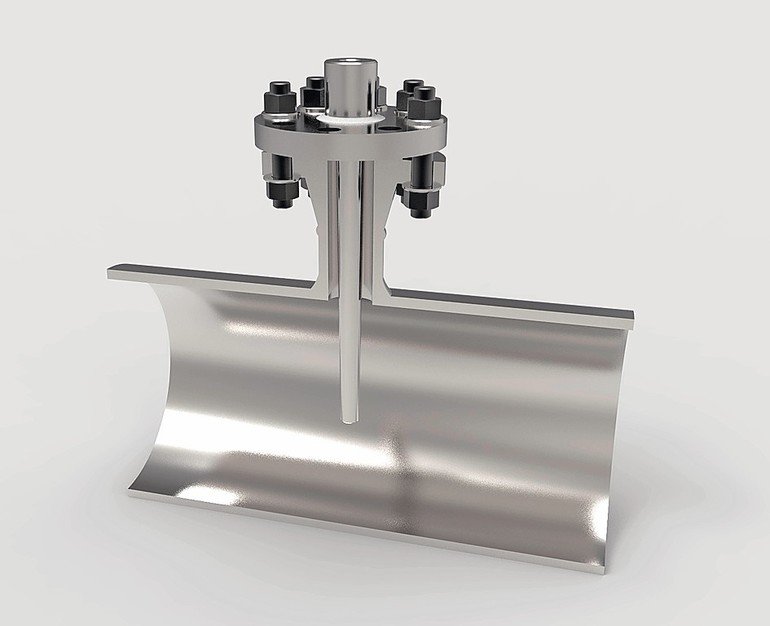
Apart from the most suitable measurement method, you also need to pay attention to certain details of the thermowell design. An insertion length of 75 mm is sufficient for an electrical thermometer in a screw-in thermowell, for instance. On the other hand, this length will be too short for a solid-machined thermowell with a flange and significant measurement errors must
be reckoned with.
Thermowell calculation
Operators are increasingly safety-conscious, and thermowell calculations are therefore demanded for numerous applications to prevent flow velocity-induced failures. The test is generally performed in accordance with the American ASME PTC 19.3 TW-2016 standard. The predetermined thermowell dimensions are offset against the maximum process parameters, usually the given design values. If the thermowell passes this test, this completes the design of the measuring point on the process side. If not, then the user is faced with a dilemma – to which there is no truly satisfactory solution.
Modified thermowell dimensions
The simplest way to repeat the thermowell calculation and obtain a positive result is to reduce the insertion length. It goes without saying that the sensor must still be in the flow of the medium to be measured. If the thermowell is so short that it disappears inside the flange nozzle, measurement errors will be the inevitable outcome. Where reducing the length is not an option, the thermowell can be strengthened by enlarging it at the root and the tip. However, if the thermowell is modified in this way, the thermometer will take significantly longer to respond. In the worst case, the thermowell will be so big and bulky that it no longer fits in the flange nozzle or in the threaded/weld-in sockets.
Alternative solutions
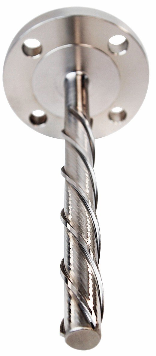
If a solution cannot be found to the problem described above despite intensive efforts, you will be obliged to consider alternatives which, however, are frequently outside the scope of ASME PTC 19.3 TW-2016. One such solution might be to use a thermowell with a ScrutonWell design. The helical stem reduces the excitation causing vibration by more than 90 %. ScrutonWell thermowells are therefore suitable wherever conventional designs fail the wake frequency calculation.
Another possibility is to switch from invasive to non-invasive measurements and use a surface resistance thermometer (mounted with a pipe clamp). If this measurement method is not feasible either, you will probably have to reduce the high flow velocity by installing a so-called pipe expansion.
This design solution is likewise recommended in many plants where the pipes have small nominal diameters. Alternatively, the thermowell can be installed at an angle in order to increase the available insertion length and optimise the flow. These two approaches can also be combined.
www.cpp-net.com
Online search: cpp0118wika
Hall 11, Booth C56
Autor: Kai Grabenauer
Product Manager,
Wika


