


Rotork plc is a listed company with its headquarters in Bath in the west of England. Starting in the 1940s as a small engineering workshop, the corporation is now the internationally leading designer and manufacturer of actuators, control systems and accessories. Corresponding devices and solutions are used, inter alia, in the fields of oil and gas, water/wastewater, navy, in mining and power generation. In 2016, around 3,700 employees worldwide achieved sales of approximately 590 million British pounds. Rotork Fluid Systems, one of five business areas of Rotork plc, specialises in production and support of hydraulic control systems. In addition to production sites for serial production in Sweden, Italy and the U.S., the Lower Saxon Melle nearby Osnabrück, Germany, is an important site for manufacturing non-series tied valve actuators. The roughly 60 employees do not only build and sell control valves for oil and gas pipelines, but also for water treatment plants, wastewater treatment plants, ships and tankers.
Implementation of high demands
Actuators help to control all the processes taking place in a petrochemical company. Hence, they prove indispensable for a smooth and secure operation. That‘s why actuators from Rotork are installed in countless storing and export systems all over the world that move, store and load oil and liquid gases. The respective processes require a lot of the actuators. Complex runs of multi products between tanks and loading facilities have to be coordinated. In these sectors the actuators are used, for example, for the precise controlling and monitoring, as well as the continuous visibility of all operations. Moreover, they ensure high security and provide shut-off emergency aid.
Rotork Fluid Systems recently built six actuators for an oil pipeline in the Arabian region. For the first time, the actuators are equipped with the logic relay system PLC logic from Phoenix Contact. In this solution a hydraulic drive opens and closes the valve with a quarter turn of the flap. The valve receives the command to do so either by way of the buttons on site or centrally from the control room by way of potential-free contacts. PLC logic executes the command for opening and closing, checks the pressure as well as the runtime of the pump and takes on the end position control. “Basically, the entire system is based on the controlling by the logic relay system PLC logic”, confirms Friedrich Wöstehoff, who works as application engineer at Rotork Fluid Systems in Melle, Germany.
Reduction in space requirements
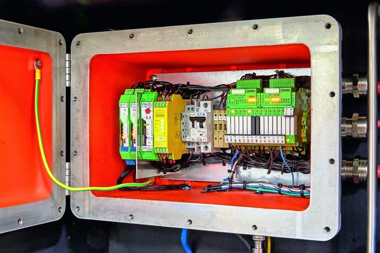
The valve actuators from Rotork stand out due to high security and reliability. This is achieved, for example, through a pressure accumulator that, in case of a power failure, still provides enough power in the form of oil pressure to be able to close the valve reliably. Furthermore, the Rotork drive products are designed for particular climatic conditions such as low temperatures up to -60 °C. Numerous components from Phoenix Contact like the hybrid motor starter Contactron, the PSR safety relay or the signal conditioner MACX Analog Ex-Namur provide for reliable operation. Wöstehoff explains: “We already use a broad range of switching devices from Phoenix Contact, so we asked the sales representatives of the company to give us some advice when we were looking for a compact and expandable solution for valve actuation. In addition to low space requirements, the ratio of price and functionality was important to us.” The entire electrical equipment of the actuator for oil pipelines is housed in a compact, gas-tight cast iron control cabinet for flameproof enclosure with Ex d degree of protection and bolted with massive nuts.
Linking of maximum 48 I/O signals
Using logic modules in an application usually requires separate interface blocks such as relays or optocouplers that are installed before or after the in- and outputs. The PLC logic logic relay system now combines the logic and the interface level with pluggable relays to one unit. This eliminates the wiring efforts and additional relays. In addition to the PLC logic module, the solution consists of the PLC-Interface relay system and the intuitively operable Logic+ programming software. The units that were created by plugging in the logic modules onto the relay without any tools continue to offer all advantages of the small coupling relay. This includes the simple bridging of the spool and contact side, the comfortable connection in screw or push-in technology as well as the quick exchange of worn out relays. Due to the integrated logic control, all contacted relays can now be programmed freely.
Depending on the relay module used, every connected relay can be configured as an input or output. Thus, the logic unit is flexible regarding the number of I/O signals used and therefore can be adapted to the respective application. The stand-alone logic module is a device that processes 16 I/O signals on an overall width of only 50 mm. To do so, the logic module just has to be plugged into eight relay modules that are in a row. In addition, there are another eight digital inputs on each logic module. Two of these inputs can be configured in such a way that analog voltage signals (0…10 V) can be processed as well. Should the user require more I/O signals, combining a basic and two extension modules makes it possible to connect a maximum of 48 I/O signals.
Programming without prior training
The easy run software Logic+ allows for a quick programming of the logic relay systems, which any electrician can carry out without special training. To do so, he only needs to have general knowledge of circuitry and digital technology. Ladder (LD) and function block diagrams (FBD) are created, for example, by selecting the relevant functions and their connection using drag & drop. “Any employee who has ever worked with traditional relay switches and is familiar with a circuit diagram can learn the system easily”, says application engineer Wöstehoff.
The representation of PLC logic in the hardware editor supports the intuitive operation. Besides, the user can simulate and test the whole program offline on his or her computer. Afterwards it can be exported to the logic module and be tested online in ongoing operations. For this, the user only has to overwrite the single I/O signals in the Logic+ hardware view. Basic functions, such as AND, OR and NOT, are complemented by special functions, such as counters, seven-day timers or mathematical functions. In addition, the range of functions also comprises bit memories for digital and numeric results and time variables. It is possible to configure them in the software in such a way that all the results remain unchanged in case of a voltage drop. The program can also be read back from PLC logic. Information like individual designations and comments of data elements do not change. By not exporting the program sources, the read back can be generally prevented.
Transmission via configuration stick
The compact design of PLC logic was a good fit for Wöstehoff. “We used to map the functions with conventional relay technology, which used to take up more space for field connectors. We were also not as flexible as we are now”, the application engineer explains. With PLC logic, the required number of inputs and outputs can now be assigned precisely to the individual PLC-Interface modules. The system can be extended with additional modules as required. “The possibilities of PLC logic go beyond mapping relay functions. With the logic relay system, we can map lifetime monitoring and even time links – a traditional controller uses much more space and is more complex in terms of the engineering”, says Wöstehoff.
The transfer of the logic in digital data also accelerates the implementation. The program for the valve controller in the first system was simply copied to a configuration stick after a successful test and then transferred to the five remaining valves that are equipped identically. “With conventional relay technology, we had to wire the logic as ‚hardware‘ five times”, says the application engineer. Subsequent adjustments in the construction – commonly last-minute – can easily be implemented. This is made possible by changing and adding inputs and outputs as well as the quick modification of the project in the software. “Finding errors now is more structured and we can issue more notifications to the customer, are more flexible and even special requests can be satisfied. Moreover, all this is comfortable and easy to handle”, Wöstehoff finishes.
Suchwort: cppPC117phoenixcontact
Author : Thorsten Knöner
Sales and Marketing,
Phoenix Contact

Good to know : Logic relay system
The PLC logic logic relay system can be integrated into various networks via optional adaptable ethernet gateways. So the user is able to set up a bidirectional communication with the higher-level controller to carry out remote control tasks and to visualise and diagnose the application. In order to do this, he or she has to link the logic modules via a connecting cable to the gateway, so that they can exchange data via Modbus/TCP, Profinet or Ethernet/IP. To integrate the different gateways into programming tools of the superimposed controllers configuration files in ESD or GSDML format are available. In doing so, the transferable process data can be incorporated and allocated from PLC logic to the respective programming environment without problems.


