A strength calculation for thermometer thermowells guarantees greater operating reliability for all types of plant in the planning phase. Expensive measuring point failures, and the associated risks and downtime, are thus prevented upfront of commissioning. With complex measuring points, an intensive discussion with the plant operators can also lead to an efficient design solution.
Kai Grabenauer
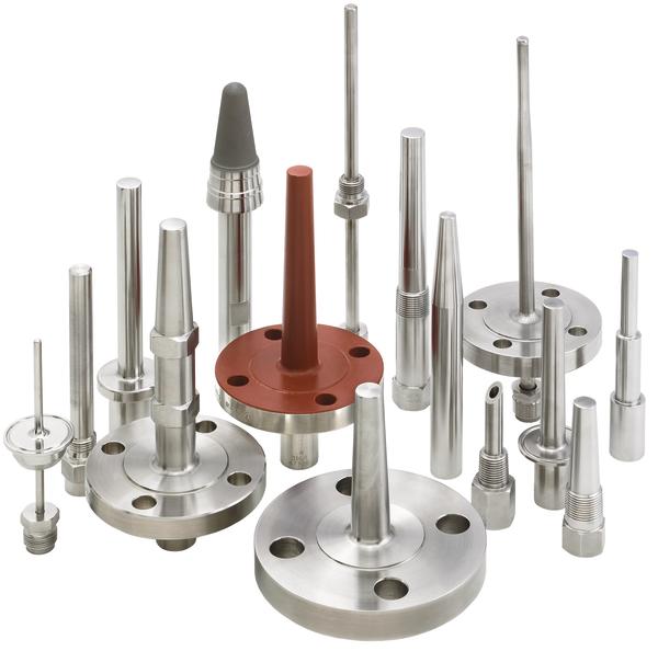
Thermowell calculations are increasingly important as a mathematical confirmation of the ability of thermometer thermowells to withstand static and dynamic loads under process conditions. Whereas in the past, the design of thermowells was for many years determined by experience, today a thermowell’s dimensions are matched to the process computationally. The most common standard worldwide for this purpose is ASME PTC 19.3. A calculation in accordance with ASME PTC 19.3 (Performance Test Code of the American Society Of Mechanical Engineers) is based on the principles established by J.W. Murdock in 1959. The “Stress Analysis of Thermowells“ by John E. Brock (1974) and simulations using finite element methods are other possible calculation bases. The rating/load tables for thermowells included in DIN 43772 derive from the calculations by P. Dittrich (1964) ; unlike PTC 19.3, they also consider fabricated thermowells built into pipes, which are an important component of this German standard.
ASME calculations
ASME PTC 19.3 applies to flow velocities up to 95 m/s; it specifies the minimum dimensions that can be computed for the root and tip diameter of solid thermowells. The pressure, temperature, density and flow velocity of the medium are required as process data. The insertion length, root, tip and bore diameter as well as the material are needed for the thermowell. The results of the ASME calculation are separated into static and dynamic values. The former category principally refers to the permissible static process pressure and the maximum insertion length in relation to buckling under static pressure load. The natural frequency fn and the wake frequency fw are the most interesting dynamic results of the thermowell computation.
The flow velocity of the process medium and the thermowell tip in the flow have an influence on the wake frequency fw. The physical fundamentals of the Kármán vortex street are represented by fixed factors. In addition to the insertion length and the temperature-dependent material data for the thermowell, the calculation of the natural frequency fn also includes variable factors, which are defined in ASME PTC 19.3. If the wake frequency fw is the same as the natural frequency fn, the thermowell will be in resonance. The maximum value of the fw/fn frequency ratio according to PTC 19.3 is 0.8. This safety factor of 20 % to resonance, for which the frequency ratio would be 1, avoids oscillation and with it damage to the thermowell through cyclic loading around the root. A simple representation of the dynamic computation results can be output as a diagram, allowing the correlation between the insertion length L and the flow velocity to be discerned directly.
The most effective way to improve the frequency ratio is to reduce the insertion length of the thermowell. The simplest procedure is to shorten it, though it should be noted that the insertion length must not be less than the height of the flange nozzle. If so, this option must not be used and the thermowell can instead be supported by an anchor in the nozzle. This shortens the freely vibrating component of the thermowell beneath the anchor in such a way that damage due to oscillation in the thermowell can be mathematically eliminated. There are two possibilities for sizing the anchor support: either the anchor can be suitably fastened to the flange nozzle inside diameter, with a small air gap of about 0.1 to 0.2 mm from this diameter, or the anchor diameter can be oversized by approximately 1 mm, then individually adapted at the mounting point by grinding, turning or filing for mounting to the corresponding fitting. The design of the anchor also varies. There are 3- and 4-point supports, which can be either welded or solidly designed with the thermowells as well as anchors manufactured from a single piece. The machined surfaces on the anchor enable the process medium to flow around the thermowell and also above the anchor, helping to improve the heat transfer.
The most obvious measure, namely rein-forcing the thermowell by enlarging the root and tip diameter, is only rarely used. This modification has a minor influence on the computation results in addition to shortening the insertion length. On the negative side, however, there is a deterioration in the response time of the sensor to changes in temperature.
Online-Info www.cpp-net.com/2309438
Share:


