Processing systems fall into the area of conflict between achieving the greatest possible level of safety for personnel, machines and the environment and the most cost-effective way of operating. Legislators have obliged system operators to comply with all applicable local rules and regulations in matters of operational safety. To meet these high requirements, a suitable and reliable safety-related system is needed. This system should not impact the industrial production process and must put the system into a safe state in the event of a dangerous situation.
Dipl.-Ing. (FH) Volker Hirsch
Safety-related measures minimise potential hazards. These measures protect personnel, the system and the environment. More and more automation technology components are being used to this end. The proper functioning of these systems and components is grouped under the heading “functional safety”. As an application-oriented standard for the process industry, IEC 61511 serves as a guideline for planning, implementing and operating safety-related systems in process plant. These systems, consisting of controllers, sensors, and corresponding actuators, guide the process into a safe state if defined limit values are exceeded. Siemens Automation & Drives (A&D) perceives the following trends in safety-related systems:
- Better integration of the safety system into the process control system
- Flexible and scalable safety systems
- Safety-related communication all the way down to the field level
- Support throughout the total safety lifecycle
- Increased field diagnostics to enable the test interval to be extended
Other bodies and organisations are also addressing these trends. The ARC Advisory Group has outlined the necessity for integrating and supporting the safety lifecycle. The first edition of Namur Recommendation NE106 concerns the extension of test intervals for the safety equipment of process control technology by increasing field diagnostics.
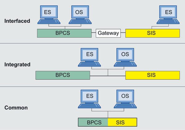
The degree of integration between the safety and process control systems can be divided into four levels: separate, interfaced, integrated and common. With separate integration, the safety instrumented system (SIS) and the process control system (PCS) exist side-by-side with no data exchange between the two. They are based on different hardware and configured by means of different engineering systems. With interfaced integration, there is also a gateway for the exchange of data between the SIS and the PCS. With integrated integration, different hardware is used for the safety-related and standard control systems, but SIS and the process control system have a uniform visualisation system and share the same engineering, operating and servicing tools. Common integration goes a step further: with common systems, the control and safety technology run on the same hardware, i.e. both systems use the same controller and bus components but different I/O modules. In addition, the same tools are used for operating, engineering and servicing the safety and control technology. Standard and safety-related programs run in parallel and independently of each other.
Flexible safety systems
The safety-related Simatic S7–400FH system for process automation is suitable for all types of integration due to its high degree of modularity and flexibility. Each system or process requires different degrees of redundancy to satisfy the individual safety and availability requirements. One of the outstanding features of this SIS is its flexible modular redundancy (FMR). This model allows the implementation of fault-tolerant architectures that are specially tailored to individual tasks and that maintain the process without reducing the level of safety, even if several faults occur at the same time. Even high availability requirements can be satisfied thanks to the ability to physically separate redundant components (e. g. up to 10 km with a failsafe CPU). The degree of redundancy of the individual architecture levels, such as the controller, peripherals and field, can be separately defined and the system components satisfy the requirements for SIL (safety integration level) 3 even without redundancy. Thus, each protective circuit (safety instrumented function – SIF) can be designed according to the individual safety and availability requirements. In addition to safety-related architectures with distributed I/O module groups, it is also possible to have a direct fieldbus connection for Profibus PA devices. The use of couplers and intelligent field distributors moreover allows redundant Profibus PA ring structures.
The advent of modern fieldbus technologies in field communication has already generated savings. Further potential economies result from the additional transmission of safety-relevant signals via these same standard fieldbuses. Profibus, for example, can be used in both standard environments and hazardous areas. Based on Profibus DP, Profisafe is the first IEC 61508-compatible communication standard to allow both standard and safety-related communication on one bus. The following measures are incorporated in Profisafe to satisfy SIL 3: consecutive numbering of the safety message frames, transmission of a time expectation for incoming message frames and their acknowledgement, identification between the transmitter and receiver and additional data security (cyclic redundancy check – CRC). Thanks to these measures, the possibility of a bus communication failure is completely ruled out and the user benefits from Profibus networks that have already been designed for safety-related communication. Certified failsafe communication between the CPU, distributed process I/Os and safety-related process instruments is thus guaranteed.
Safety lifecycle
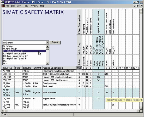
In IEC 61511, the safety lifecycle is divided into three main phases: analysis, implementation and operation. The safety needs of a system are determined in the analysis and the requirements for a protective system defined accordingly. The actual level of safety reached by selecting the technologies and architectures is verified and documented during the implementation period. In the operating phase, the activities required for operating, servicing and modifying the safety applications must be recorded. The Simatic safety matrix was developed to be able to optimally support the user with all safety aspects over the entire lifecycle. It is based on the proven principle of a cause-and-effect matrix and can be optimally applied to processes in which defined conditions require defined safety responses. The cause-and-effect matrix graphically displays the links between events (causes) and measures (effects). In this way, large amounts of data can be visualised in a clearly structured and compact graphic. By using the safety matrix from the analysis phase onwards, safety logic (including bypasses, delays, etc.) can be documented according to the cause-and-effect principle. In the engineering system for Simatic PCS7, the safety matrix automatically generates the safety-related application for the safety system and visualises it on the operator panel. It also facilitates change tracking, including automatic versioning. During operation, the safety matrix affords a clear display and control of the safety applications. The matrix thus provides continuous support from documenting the request, configuring, programming and commissioning to operation, servicing and modification. In this way, it reduces the engineering and servicing costs for the SIS.
Increased field diagnostics
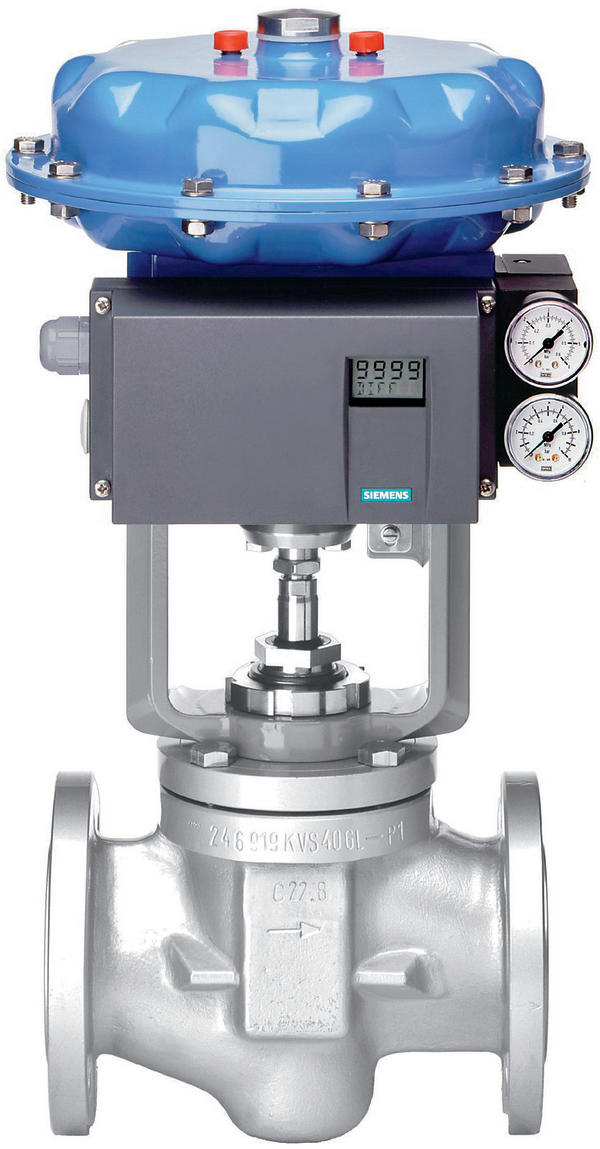
The safety-related system is supplemented by functional process safety applications, such as the valve start-up test (partial stroke test) for testing protective valves. Checking valve functions during operation permits a clear indication of increased diagnostics for safety shut-off devices and enables the test intervals for protective valves (complete test) to be extended while simultaneously maintaining the safety level. This reduces downtimes and maintenance costs. In addition to partial stroke tests that are carried out with the aid of a position controller, the safety system of the safety-related Simatic S7–400FH PLC also provides a solution integrated into the process control system: the pre-configured logic carries out the valve start-up test and an optional solenoid valve test. At the same time, the system makes checkback signals available by means of the valve function and outputs corresponding alarms. The associated variable block for a Simatic PCS7 OS operator station gives a quick overview of states and alarms, allows access to configuration parameters and provides information on the result of the last partial stroke test. All relevant analogue values, such as setpoint and actual values or messages and alarms, are archived. In addition, the tests can be automatically logged.
By implementing the trends outlined here for the structure of safety-related systems, the supplier satisfies the high requirements demanded in the process industry: in the event of danger, the system can be put into a safe state at any time. Thanks to the user-friendly concept, savings in terms of investment and operating costs can be achieved while simultaneously maintaining safety levels, as shown by the following examples: one engineering system and one operator system for process control and safety, reduced training and stocks of spare parts due to the integration of the safety and process control system, redundancy only where it is actually needed thanks to the flexible and scalable SIS, reduced wiring owing to safety-related communication all the way down to the field level, reduced engineering costs thanks to the safety matrix and one tool for all phases of the safety lifecycle as well as reduced downtimes owing to the integration of the partial stroke tests for extending the test intervals.
cpp 407
Partial-Stroke-Test
IEC 61511
Namur NE 106
Share:


