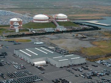
The Fluxys LNG Peak Shaving in the back port of Zeebrugge (Belgium) dates from 1978. Here, liquid natural gas (LNG) is stored, which is supplied by trucks from the LNG-terminal in the front port of Zeebrugge. When the gas demand is higher than the primary supply (through pipelines from Norway and Great Britain or LNG-tankers), the supply in the LNG Peak Shaving is heated to 2 °C and sent into the network.
The heating of
LNG (kept at -162 °C) to gaseous form (around 2 °C), takes place in a re-gasification installation for which the energy is supplied by gas burners. To keep the exhaust gases of this installation as pure as possible (free of CO and NOx), specific controls are used on the burners, whereby the amount of air supply to the burner basins is a key factor. To better control the supplied amount, the pressure measurement control on the air supply was replaced by a mass flow meter. This more accurate control increased the efficiency of the burners and ensured compliance with the local VLAREM exhaust regulations for CO and NOx.
Natural gas distribution
As with the Belgian energy sector, the market for natural gas distribution has separated the network management from the commerce. In Belgium, Fluxys is the company responsible for the transport of natural gas. The LNG Peak Shaving installation dates from before this separation and was started in 1978. In those days, the installation was at the end of the gas line (natural gas entered Belgium from The Netherlands) and its single purpose was to gasify stored LNG in periods of high demand (winter), and send it into the network to maintain a constant pressure. In a period of low consumption (summer), natural gas was taken from the pipelines and liquefied for storage by means of a liquefier installation. Today the natural gas is supplied in liquefied form by trucks from the LNG-terminal.
Zeebrugge is an important transnational centre for the distribution of natural gas. It has the capacity to handle 15 % of the natural gas consumption of continental Western Europe. Norwegian and British natural gas is supplied through pipelines, and LNG-tankers like the Methania deliver gas via the front port of Zeebrugge.
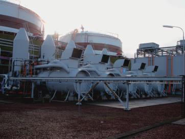
Evaporator for LNG
Today, the Peak Shaving installation consists of three parts. The first part is the intake. Trucks transport 41 Nm³ of LNG at a time from the LNG terminal at the front port of Zeebrugge to the intake. The second part is the LNG storage. This consists of two overground tanks, which each have a design capacity of 57,250 Nm³. The gas is preserved in liquid condition at -162 °C. The cryogene boil-off gas (LNG which evaporates at the surface) is diverted by compressors and pumped into the gas network.
The third part is the evaporator. It is activated when users at the storage ask for it. When the installation is in stand-by (cryogenic pumps cooled, …), the evaporators can deliver natural gas within twelve hours. When the installation is not in stand-by, it takes twenty-four hours to deliver gas. This may seem a long time, but it is more than adequate. The gas distribution network with 3,800 km of conduit-pipes (600 or 1200 mm for 66 and 80 bar) is an important buffer. When the users of the natural gas distribution network require a capacity which makes it necessary to activate the LNG Peak Shaving installation, the buffer in the pipes provides enough time to start up the evaporators on the installation, without causing a spectacular pressure drop.
There are five LNG evaporators in the LNG Peak Shaving installation. They consist of a heated 40,000 l water basin and a gas spiral, which runs through it. This spiral is the heat exchanger in which the transition of LNG/gas takes place. Each evaporator can evaporate more than 80,000 Nm³/h of LNG. This natural gas is then pumped into the conduit-pipes. The energy to evaporate gases is delivered by two burners with a capacity of 9 MW each. Their exhaust gases bubble through the water basin and heat up the water while it improves the thermal dispersion between the heated water and the gas spiral.
Control through air flow
The burners are controlled by the air flow of the ventilators. The correct amount of air delivers a higher combustion return, but the air control also has its effect on the environment. VLAREM (Flemish Environmental Administration) makes it necessary to minimize the CO and NOx, which requires a correct calibration of the combustion air supply. Too little air supply creates CO, and too much air supply results in NOx. However, too much air, to a certain level, also cools down the flame and reduces the formation of NOx (NOx is formed at high temperature, starting at a flame temperature of 800 °C).
Previously, a pressure measurement was used to control the air flow. This system was based on the classic pitot’s tube over which differential pressure was measured. The maximum air velocity is about 60 m/s in a 400 mm diameter tube. The created overpressure is limited to 235 mbar and the differential pressure, used for control, is not higher than 6.5 mbar. Based on such a small measurement window, it is difficult to measure or control accurately, but this was the only measurement principle available at the time. At Fluxys, evolutions in measurement are carefully followed up and, within budgetary agreements, the installations are kept up to date.
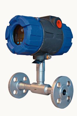
Tests had been conducted with positive displacement meters, a measurement system based on a little paddle rotated by the flow. This worked very well in the summer. In the winter, this meter has the tendency to freeze up. In 2002 Fluxys tested the Thermatel TA2, provided by Magnetrol. The unit passed the test and TA2’s were installed on all burners. The Thermatel TA2 is based on thermal mass flow measurement. The choice for Magnetrol’s Thermatel TA2 is based on good experiences with the material and the supplier (Echotel ultrasonic level switches are already used on the oil reservoirs of the boil-off compressors), but also on technical features like the wide application range of the instruments (they are calibrated for a range between 12,000 and 19,000 Nm³ and have a turndown ratio of 100 : 1).
Thermal mass flow meter
With this type of measurement, two RTDs (resistance temperature devices) at a fixed distance from each other, are placed in the tube through which the gas flows. One RTD measures the ambient temperature (the gas temperature), and the other one is heated to exactly 20 °C higher than the process temperature. The gas flow cools down the heated RTD and makes it necessary to continuously add heat. The energy, neces-sary to keep this delta of 20 °C, is the measure for the gas flow, which is the mass flow that passes by the sensor. The microprocessor in the meter compares the consumed energy with a calibrated curve and translates the energy consumption to mass flow. This measurement is insensitive to vibration and therefore very useful. It is insensitive to pressure and temperature because it is a comparative measurement. The TA2 sensor measures the process temperature and compensates the mass flow in function of this temperature because the heat transfer at various temperatures can be different. A limitation of this type of meter (independent of the brand) is that the instrument does not react to sudden flow changes (the temperature stabilization takes a while), but this limitation is not important for this application.
cpp 449
Mass flow transmitter Thermatel TA2
LNG storage by Fluxys
Share:

