In the production of APIs (Active Pharmaceutical Ingredients) and Intermediates exceptional facility engineering is required to accomplish the safe transport and the filling and discharge procedures. In order to assist the user in selecting the appropriate containment system, the ISPE Good Practice Guide enables the classification of facilities in terms of containment. For control purposes, measurements are taken of the dust exposure while the containment system is being docked and/or undocked and of the surface concentration at the facility components.
Richard Denk
When planning that facility, it was im-perative to develop an innovative flexible containment system which met the demands of the production of Intermediates and APIs providing a DEL (Design Exposure Limit) of small 250 ng/m3 TWA. In order to eliminate a time-consuming and costly cleaning validation of the packaging units, disposable packaging material had to be provided. A verified disposable containment system for such low limits did not exist at that time and had to be newly developed. The disposable packaging material and its design in particular were supposed to include the following qualities: suitable for products with different flow behaviors, best by self-emptying due to the geometry of the disposable packaging material or dischargeable by appropriate agitation units. A permit for handling hazardous materials allowing the transportation of the products beyond the factory without secondary packaging was recommended. The packaging material was to be approved for the transport by ship, truck and rail. The expenditure of the disposable packaging system played an essential role because a great number of packaging materials are filled or discharged annually.
Flexible container
A variety of most different containment systems had been examined and, with the help of a risk assessment, the FIBC (Flexible Intermediate Bulk Container) was finally chosen as appropriate packaging medium meeting all requested issues without any restriction.
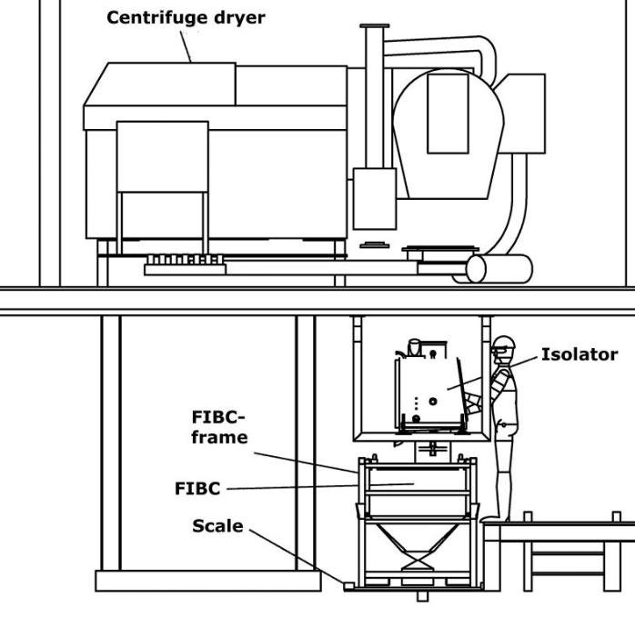
In order to achieve the high containment, the FIBC must be equipped with two in-liners each at the inlet- and outlet connecting systems. The inner in-liner is filled with product. The outer in-liner provides double protection and serves as connection to the prod-uct transfer system. Both in-liners are safeguarded by the FIBC’s outer shell during transportation.
Containment system with isolator
When connecting the product transfer system, the requested containment level only is achievable by means of an isolator. In order to constantly maintain the containment, the isolator is operated under continuous subpressure (-50 up to -70 Pa) and with twenty fold air exchange. The subpressure is controlled via a frequency converter at the vacuum system which increases the performance in case of a leak and thus prohibits particle emission. Each individual sequence of operation concerning the connection of the FIBC was closely examined during the Design Qualification (DQ) and its implementation was recorded in the requirement spec-ification for the design version.
The connection of the outer in-liner to the isolator was considered to be critical. The outlet connecting system of the in-liner was supposed to be adapted to the still closed isolator and its tightness to be checked. The tightness test system is located in the connecting system for the outer in-liner and is verified and released via the control unit. Following the tightness test of the outer in-liner, the isolator is opened by means of an RTP (Rapid Transfer Port) from inside. Due to the subpressure in the isolator, the inner in-liner is automatically pulled into the isolator. Inside the isolator there is another connecting system allowing a safe and contained connection of the product in-liner. The request was to prevent any and all dust formation and any open product handling in the isolator in order to minimize a difficult cleaning procedure of the isolator and to dismiss negative influences on the containment to be achieved.
Transportation and reception system for the FIBC
Since the FIBC is a flexible packaging me-dium, it was decided during risk assessment to put it in a frame and to move it on a pallet truck. That frame is also needed for the positioning of the FIBC into filling- or discharging positions executed by a lifting column. The design of the lifting column again proved to be critical. On account of the solvents used in the room, the lifting column must be entirely made of stainless steel. Other than the usual plastic coverings, the lifting sledge is furnished with a stainless steel blind at its front.
An agitation unit rocks the FIBC outlet in order to support the product flow exiting the FIBC. The agitation unit is adjustable in height so that it can be moved to the FIBC outlet after the FIBC frame has been positioned.
The system was set up with dummies for a mock-up. Each individual step was tested by the operators. An early involvement of the operators in the future facility design had already proved to be worthwhile in former projects. The cleaning procedures as well as the extraction of parts for cleaning were tested in order to conclude the design of the components and to release it for manufacturing.
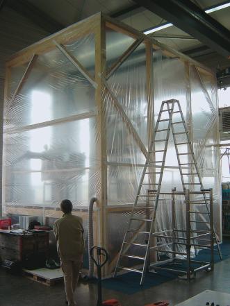
Particulate measurement in conformity with Smepac
On account of the new technology, the particulate measurement was supposed to be carried out at the facility components when running the FAT (Factory Acceptance Test). For this purpose, the facility components were erected in a wooden frame construction which was fitted tight inside with a liner. All cable routings for the facility control were closed tight. An area allowing staff access into the enclosure was provided. Lactose served as surrogate material. The access to the area where the facility and the enclosure had been erected was declared as lactose-free zone and the doors were marked prohibiting the access of unauthorized staff. The transportation of the lactose from a discharge container outside the hall was conducted via a pneumatic conveyor system into a vessel above the enclosed room. That vessel was supposed to simulate the dryer which discharges its contents into the FIBC in the course of measuring. Another step was the flushing air of the room with cleaned air, where the measuring should take place (HEPA filters, threefold air exchange per hour). The facility components were cleaned with purified water because apart from air samplers also wipe tests were made.
Smepac defines the position for IOM-samplers exactly at the interface or above it. In contrast to Smepac, the IOM samplers were installed underneath the undocking spot while the FIBC was filled in order to catch any particles in the filter in case of a dust exposure as such particles are forced downwards due to airflow. Therefore two samplers were positioned approx. 10 inches underneath the undocking spot and another two in direct proximity at the undocking spot in compliance with Smepac. More samplers were attached at the glove ports at the isolator and at the filters, near the respiratory areas of the operators and in the room. Persons who were present during the measuring procedure had to wear new and non-contaminated protective garments, gloves and headgear before entering the enclosed room.
An additional action for the measurement records was the video monitoring during the entire period of measuring. It allowed to document individual operational steps even after the test or to define possibilities for improvement. The subsequent creation of the SOPs (Standard Operator Procedures) is facilitated as a result of the video documentation. Prior to the start of operation each single move can be explained to and discussed with the operating staff supported by the video recording. In addition to the air samples, wipe tests were carried out at critical areas in order to determine the surface contamination. Each discharge and filling process was repeated three times and recorded. The samples were analyzed by a laboratory provided by the end customer.
Conclusion
The Good Practice Guide is a competent document for the implementation of particulate measurement of facility equipment for high potent substances. There is, however, no guarantee that the containment measured by using surrogate material such as lactose will be identical with that of an API but this procedure offers the benefit of comparing different facility technologies referring to containment.
Hall 6.0, Booth J9
cpp 458
Directly to Hecht Anlagenbau
ISPE Good Practice Guide as book
ISPE-Homepage
Share:


