Standards for plant safety based on instrumentation and control systems have existed in Germany since the late 1980s. Risk assessments are carried out according to DIN V 19250 and DIN V 19251, and the safety functions of plant components are categorised into protection classes from 1 to 8. DIN V 19250 and 19251 have now been superseded by IEC 61508 and 61511. These IEC standards have a wider range of application than the previous DIN standards. They are emerging as increasingly important, especially in the chemical and petrochemical industries as well as in all areas where hazardous materials are handled.
Wolfgang Perenthaler
The earliest implementation of the new IEC standards began two years ago in the UK. The hazard potential of an industrial plant or a plant component is determined, as in the DIN system, using a risk diagram. A safety-relevant part of the plant equipment is examined in detail with the help of a risk assessment. The criteria used for this purpose are very similar to DIN.
This assessment determines whether or not the component in question has a safety function and if so, the hazard potential it is intended to protect against. The resulting Safety Integrity Level (SIL 1 to 4) describes the measures which need to be taken to control the risk. The entire measurement chain has to be taken into account in order to derive the SIL. The application can then be instrumented in two different ways:
- Reliance on proven technology already installed in the plant (‚proven in use‘ reliability)
- Instruments that have been SIL-qualified by the manufacturer
SIL based on proven in use instrument technology
Plant components are considered ‚proven in use‘ if a minimum number of them have been used over a defined period of time in the same application, or in similar applications, and their function is considered to be reliable. IEC 61511 stipulates a total operating time of at least 30 million hours (including all instruments used). In addition to IEC 61511, Namur recommendation NE 93 also describes criteria for ‚proven in use‘ reliability. This SIL rating is therefore based solely on empirical data recorded by the user. If the reliability criteria are fulfilled and no malfunctions (or only acceptable, passive malfunctions) have occurred, the user can classify the instrument up to safety level SIL 2.
The basis for this interpretation, i.e. the SIL qualification, is a comprehensive statistical analysis of the failure mode of all the affected sensors and logic units, such as a PLC or actuators. PLCs have, however, already been qualified for a number of years. The real problem here lies in the application or process itself. Where do we draw the line, in other words, or how can we obtain a meaningful result in an acceptable way? Nearly all the processes in the chemical industry differ from one another (product density, viscosity, pressure, temperature, mounting position, overflow/dry running protection, resistance, material, vessel size, etc.). Qualification according to IEC 61511 (i.e. ‚proven in use‘ reliability) is practicable only over long observation periods and, basically, only for larger companies. Moreover, the expense has to be weighed up against the potential benefit. Processes in the petrochemical industry tend to be fairly similar from one company and from one manufacturing plant to another. SIL qualification is therefore a much simpler task than in many other industries.
SIL qualification by the manufacturer
More and more manufacturers are starting to qualify their instruments according to the new standards (IEC 61508 and 61511) for functional safety. To design a measurement system correctly, the user needs comprehensive data from the manufacturer as a basis for calculating the parameters of safety-related equipment. Some instruments, like the Vegaswing 60 level switch, are already designed according to IEC 61508 – still rather unusual at present. If an instrument is developed in conformity with the above standards, it follows that all technical data and process parameters have been taken into account. The limitations of use are determined accordingly and noted in the safety manual along with key safety-relevant data.
If a manufacturer goes beyond the scope of ‚proven in use‘ reliability as defined by IEC 61511, as is the case for example with the Vegapuls 40 and 50 radar sensors, far more empirical data will be available than to individual users. This data will moreover cover the entire range of application of the instrument. The manufacturer must additionally make use of IEC 61508 to carry out an FMEDA (Failure Modes, Effects and Diagnostic Analysis). This method of determi-ning instrument reliability is still the norm at the present time. It is also the approach adopted by Vega with instruments already on the market. Since the 30 million hour rule applies here too, of course, qualification on this basis can never be achieved by instruments that have not long been introduced. The data pool can only be used to assess instrument reliability after the required test criteria have been fulfilled.
Design of an SIL measurement system
If DIN V 19250 and 19251 previously assigned each individual component in a measurement chain or a safety loop to class AK 4, for example, then the class of the complete chain was also AK 4. The situation is somewhat different with IEC. An instrument has no SIL classification, but can be used on the basis of safety characteristic values in a measurement chain that complies with SIL X. These safety characteristic values can be found in the technical documentation or the safety manual for the instrument. The probability of failure on demand (PFD) is one of the most important parameters. It represents a starting point for determining whether, and in which SIL, the instrument can be used. SIL 2, for instance, requires that the probability of failure on demand of a measurement chain be between 1 x 10⁻³ and 1 x 10⁻². In contrast to the DIN system, the PFDs of the measurement chain components are added together. It must be ensured, therefore, that the sum of the PFDs of all components with, say, SIL 2 does not exceed the value 0.99 x 10⁻². It can easily happen that a measurement chain consisting of components presumed to be suitable for SIL 2 suddenly has a sum which results in only SIL 1. Several steps can be taken to enable such components to be used nevertheless: the instrument can be paired or connected in an OR circuit (1oo2), or the prescribed test interval can be shortened. The PFD of the measurement chain is thereby reduced and the required SIL is obtained again.
Recurring functional test on an SIL measurement system
SIL also implies a recurring functional test, the cycle of which is determined by the measurement chain as a whole. The probability of failure on demand (PFD) is thus an important parameter not only for the layout but also for the test interval. Since the PFD generally applies to use over a period of one year, the test interval is likewise one year. As with WHG (Water Resources Act) overfill protection, a wet test (raising the level to the contact point or dismantling, for example) must then be carried out. There are several possible alternatives for the Vegaswing 60 level switch:
- If a Vegator 636 signal conditioning instrument is connected, a simple press of the test key suffices. When this key is pressed, the sensor is subjected to a functional test encompassing all possible fault conditions and the conditioning instrument switches the relay output accordingly. All other connected devices – i.e. the whole of the measurement chain – are thus tested as well. The test interval in this case is one or two years.
- If a Vegaswing with 8 mA/16 mA electronics is operated directly via a PLC, the PFD of the measurement chain is considerably lower and the test interval is correspondingly longer. This kind of measurement system design can lead to a test interval of five or more years in practice. The functional test is carried out by briefly interrupting the connecting cable to the sensor and generating a log of the switching states.
- If the instrument is equipped with Namur electronics, the test interval is similar in length. A wet test is still required, however.
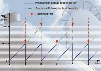
Depending on the PFD and the specified SIL, the test interval can be shorter or longer than one year. It is assumed that the PFD of an instrument is zero at the time of commissioning as well as after each test, and that the specified value is achieved after one year. A linear characteristic curve (Fig. 2) is also assumed. If the test interval is reduced to six months, for instance, the PFD of the measurement chain is halved accordingly. If the test interval is increased to two years, the PFD is theoretically doubled.
Instruments fulfil SIL 2 and SIL 3 requirements
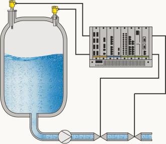
Due to its high reliability, the Vegaswing 60 series of level switches can be used with different electronic versions in measurement systems where SIL 2 or SIL 3 is required: single-channel in SIL 2 and redundantly with a “one out of two“ (1oo2) evaluation in SIL 3. The application criteria of Namur recommendation NE 79 are thus fulfilled up to hazard zone II. The Vegapuls 40 and 50 radar sensor series with a 4…20 mA output meet the requirements for use in SIL 2 applications. They can be installed for overfill and dry running protection or integrated in safety-relevant measurement systems according to SIL 2 for operation in continuous mode. In hazard zone II (SIL 3), Vegapuls radar sensors can, for example, be combined with a Vegaswing 60 (OR circuit). The advantage: continuous measurement is included in the safety concept (Fig. 3).
1oo1 or 1oo2 for hazard zone II
Another question arises particularly in connection with hazard zone II (SIL 3): how high is process availability if, instead of two independent instruments in 1oo2, only a single (1oo1 or one-out-of-one) SIL 3-rated instrument is used? Once the process equipment has been set to a safe condition by this kind of system, it must be kept there (according to the standard) until the system is fully functional again. In a 1oo2 evaluation, on the other hand, the process equipment can under certain circumstances continue to operate in spite of a defect in a measurement chain component, so that process availability is certain to remain high even in case of a failure. NE 93 also follows the philosophy of 1oo2 in this hazard zone.
Outlook
Due to the universal specifications in the extremely comprehensive IEC standards, the scope of application will spread to all industries, as it already has in the UK. For individual users, however, considerable expense is involved in investigating all aspects of functional safety and carrying out a risk assessment. Various software tools have been developed for the purpose of safety examinations, and they also simplify instrument selection and the system layout. It nevertheless remains the responsibility of the plant operator to decide which safety technology should be installed in a particular plant. Always using instruments with the highest safety level (SIL) is undoubtedly a pragmatic solution, but at the same time it leads to greatly increased procurement costs. The redundancy necessary for SIL 3 and higher, for example, noticeably affects the cost of a measurement system. Coming to terms with the new standards and applying them meaningfully inevitably involves a lot of time and effort. In the final analysis, however, this is – and is likely to remain – the best way to arrive at an economically viable solution.
cav 441
Share:


