
Today, process automation is characterised by key terms like diagnosis or asset management. Operators above all hope to cut the cost of ownership, yet at the same time increase plant safety and availability. A perfect holistic approach should therefore focus on fault avoidance rather than fault diagnosis. This also includes optimised control valve components tuned to each other and the current process.
Guido König, Jörg Kiesbauer
Control valves are used to regulate the medium flow in a process. To do so, the valve must convert the setpoint determined by the process control system into the required opening position of the clo-sure member. This conversion must be performed
- Quickly and accurately
- Reliably and without any complications
- Without high noise emission or wear
- Without a large amount of maintenance, ensuring long service intervals
- With a reliable fail-safe function and possibly an extremely tight shut-off within the valve in case of an emergency.
Optimising control valve performance minimises the life cycle and operating costs. If the control behaviour of the valve is poor, these costs can amount to several times the initial purchase outlay.
This results in a holistic asset management approach based on reliable control valve assemblies with optimised functions, careful valve sizing and selection, performance monitoring with online fault detection and maintenance information.
Control valve assemblies with optimised functions
The performance of the control valve with regard to flow and noise emission greatly depends on the quality of the closure member and the extent to which the maximum flow capacity of the valve is utilised. There is a general rule that all valve sizing coefficients, such as FL, xT and xFz, deteriorate the greater the degree to which the cv value of the available nominal valve size is utilised.
Nevertheless, some manufacturers still use very large valve bodies with large rated travels, stressing the hydraulics of the valve to the extreme only to achieve the highest possible cvs value. Other manufacturers hope to achieve quieter valves, ignoring the fact that noise is mainly generated at the vena contracta, i.e. at the closure member.
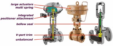
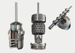
In the end, it all comes down to cost-efficient and perfectly functioning designs. It should therefore be taken into account that the closure members are expected to work without mechanical vibration, emitting as little flow noise as possible. V-port plugs with a rugged guide in the seat area (Fig. 1) are particularly beneficial, as experience has shown that the strongest flow turbulence occurs at the seat area. This is why operators usually tend to prefer four-flange bodies for small nominal sizes, as they offer a second guide for the parabolic plug in the lower body section. This is rather inefficient, however. Moreover, it is better to incorporate the second guide in the seat. A recently developed throttling system to prevent cavitation and reduce cavitation-induced noise emission (Fig. 2) can serve as an example. The AC-Trim throttling system is based on a seat-guided parabolic plug, which is uniquely adapted to the flow characteristics. Additional attenuation plates in the seat can ameliorate the xFz value even with larger valve openings.
With liquid flows and high pressure drops exceeding 40 bar, on the one hand, it is re-commendable to use valves with a „genuine“ multi-stage plug with a double guide (Fig. 2). Multi-stage parabolic plugs allow higher xFz values than radial or axial perforated plug systems. At the same time, they guarantee reliable operation because they are not susceptible to dirt.
With compressible media, on the other hand, completely different noise abatement measures must be taken. Using flow dividers integrated into the valve (Fig. 2) in combination with a V-port plug can reduce the noise level down to 30 dB. Single tones, which often occur in parabolic plugs, are practically inaudible.
If the liquid permanently evaporates downstream of the valve (flashing), multi-stage control valves are a bad choice, as the space for expansion downstream of the vena contracta should be as ample as pos-sible to prevent erosion problems. Angle valves with the direction of flow in the clo-sing direction or globe valves with a reduced seat size and the direction of flow against the closing direction, for example, offer this feature.
Despite all these complex requirements, we must not forget reliability and easy maintenance. It is therefore preferable to use throttling systems incorporating simple parts which can be manufactured to meet high quality standards. Clever valve and seat geometry designs, e.g. to reduce cavitation-induced noise as in the AC-Trim (Fig. 2), are better suited for the requirements specified above than complicated cage constructions or systems with several interlaced perforated plugs. Apart from the large amount of material required, such constructions are highly susceptible to dirt.
At first glance, the throttling systems with a cage trim commonly used in certain markets seem to have an advantage as far as maintenance is concerned, as the so-called seat retainer can simply be pulled out. However, as several seals (seat and flange) are located in the line of strain, wear will almost inevitably occur due to friction and bad alignment of the moving parts. This can considerably worsen the control performance.
Low-friction and low-maintenance stem packings, such as self-adjusting PTFE packings suitable for temperatures up to 200 °C, allow movement of the plug without stick-slip effects. PTFE becomes too soft at higher temperatures, so that other sealing materials such as graphite have to be used. This, however, considerably increases the amount of friction at the valve stem, resulting in a detrimental effect on the performance of the control valve. In many applications, there is really no alternative to a metal bellows (Fig. 1): it provides the tightest seal, optimum control performance and a long service life (approx. 10 million rated load cycles at 10% travel). At the same time, friction does not pose a problem. The metal bellows can moreover be safely monitored online using a reference volume with a pressure switch and digital positioner (binary input).
Some manufacturers swear by pressure-balanced plugs to reduce the required actuator force. Yet the sealing rings used to balance the plug increase friction so significantly that the control performance is impaired. The same applies to the tight shut-off in the valve when the valve is closed.
Reliable actuators
The actuator also plays a decisive role when it comes to achieving reliability and a good control valve performance. The following features have a positive effect on performance and reliability:
- Large effective areas reduce the negative influence of friction forces on control valve performance by minimising hysteresis and dead band (Fig. 1).
- Several spring assemblies with smaller springs distributed over the circumference offer greater accuracy and mechanical stability than fewer large springs arranged in the centre. In addition, the variability of the spring range and the stiffness of the actuator are increased.
- Diaphragm actuators have a considerably smaller hysteresis than piston actuators (up to 40% hysteresis due to piston seals), which the positioner is likely to be unable to compensate in the long term.
- Optimised actuator diaphragms equipped with a fabric insert and a sophisticated attachment to the diaphragm plate facilitate a long service life.
- Integrated actuators (Samson attachment (Fig. 1), VDI 3847) for compact assembly on the positioner minimise the problems caused by mechanical travel transmission and instability (bending, backlash, etc.) if there are high dynamic loads acting on the entire control valve (e.g. due to vibration).
Positioner as the third standard component
During the last few years, positioners have gained acceptance as the third standard control component besides actuators and control valves. They have taken the place of electropneumatic signal converters and direct transmission of a standardised pneumatic signal to the actuator. Positioners also offer greater flexibility when choosing an actuator with the appropriate spring range and effective area.
Analogue positioners with pneumatic control loops have proved their worth. They render excellent control properties, indispensable for high control valve performance, providing they have been correctly adjusted by the instrumentation and control staff.
Nevertheless, to gain additional information about the status of the control valve, separate components such as limit switches or position transmitters have to be used. These components can also be integrated into the positioner. This leads to a situation where a relatively heavy investment must be made to collect only a comparatively small amount of data, as the accuracy of the status information supplied by the analogue equipment is limited.
Digital positioners have the same optimum control properties thanks to their automatic initialisation routines and the integrated optimisation of the control loop parameters. Moreover, they allow extended positioner functionality, eliminating the disadvantages of electropneumatic proportional controllers using analogue signals.
An optimum positioner design, however, requires more than the use of microprocessor-controlled solutions, as the entire system could be subject to certain restrictions, for example a limited power supply. The digital positioner designs available on the market include simple electropneumatic signal converters as output stages and a control algorithm. This algorithm varies the signal converter current (manipulated variable) such that the valve position (controlled variable) corresponds to the specific reference variable. This kind of positioner lacks dynamics, as the sampling rate is limited due to the restricted power supply. The gain necessary to reduce instabilities is therefore also limited, ultimately leading to significant system deviations.
Output stages with pulse width modulation consume little energy, but, depending on how they are implemented, are unable to offer long-term stability. Pilot-operated solenoid valves, however, guarantee a uniform response. Control accuracy can be determined by the dead band, which is limited due to possible instabilities, in the range from 60.1 % to 60.5 %.
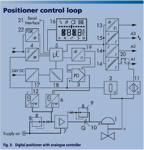
Significant progress towards good control performance has been made by using certain, completely analogue components in the digital positioner. For example, an electronic positioner control loop (Fig. 3) with digitally adjustable control parameters is superior to any digital control loop, as no time is required for signal conversion and processing. The direct, undelayed response of the controller to disturbance variables and changes in the controlled variable helps facilitate unbeatable performance.
Careful sizing and selection
When planning a plant, it is however also crucial to place the right control valve in the appropriate location. This is a task for both the plant operator and the valve manufacturer. This is basically where asset management begins.
Consequently, careful sizing of the control valve in accordance with dependable process data is vital. The sizing process comprises the following steps:
- Determining the nominal valve size according to the maximum permissible flow velocities at the valve outlet
- Determining the operating cv values and selecting the cvs value, taking into account the entire travel range
- calculating the noise emission and assessing critical operating conditions which might possibly occur (e.g. cavitation, flashing, etc.)
- Selecting the appropriate material
- electing the most suitable control valve type
Over the past few years, more extensive calculation methods to determine the cv value and noise level have been added to the ISO 60534 standard for control valves. These methods have facilitated detailed recording of the flow status in the valve. Based on experience gathered in international working groups, there is a tendency above all amongst manufacturers to apply calculation methods which do not require the use of measured valve coefficients. We consider this strategy a risky one, as optimum sizing accuracy is impos-sible without measured valve coefficients.
Performance monitoring
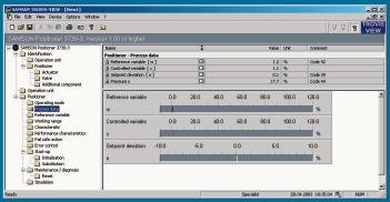
In control valve assemblies with a microprocessor-controlled positioner, this positioner serves two purposes. Firstly, it performs its initial task of controlling the valve opening exactly according to the setpoint. Secondly, by processing the signals and algorithm, it also monitors the entire control valve as well as collecting and evaluating valve data. When digital positioners with an automatic start-up function are used, operators can rest absolutely assured that their plant will always work with opti-mally adjusted control valves. During the initialisation routine, the positioner itself additionally generates clear fault and alarm messages which either stop or restrict the start-up process. This allows the operator to intervene directly (Fig. 4).
This principle whereby the positioner uses its own components to gather information, analyse it and generate fault and maintenance status messages appears to be fundamentally preferable. The method more or less forgoes the use of additional, possibly fault-inducing sensors. It moreover dispenses with specific diagnostic software, which would inevitably necessitate further training.
Despite the various possibilities for collec-ting status and maintenance information about the entire control valve assembly using the digital positioners, the primary goal is to guarantee continued control operation even when faults occur. The I/P converter emergency mode, for example, keeps the control valve functioning if the displacement sensor system is defective and outputs an appropriate error message.
In principle, the positioner supplies various signals which can be compared and evaluated to detect faults (Fig. 5). In addition to the reference variable (setpoint), the controlled variable (valve opening) and the error signal that is directly derivable from this, the output signal for the actuator and the valve travel are available. Using these signals, the positioner can generate error messages automatically (Table).
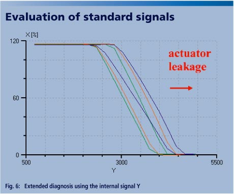
The smart evaluation of standard signals, such as the valve opening X, setpoint W and internal control signal Y (e.g. I/P converter), always enables detailed detection and evaluation of control valve parameters like friction, actuator leakage, supply pressure, spring force and actuator load during operation. Figure 6, for example, clearly illustrates how, as a function of the valve position X, the internal control signal Y is displaced rightwards compared to the initial characteristic as a result of a significant increase in actuator leakage. When it comes to fault diagnosis, many manufacturers tend to focus on the increased friction parameter, because increased friction could lower control valve performance. If we wanted to be provocative, we could say that the main purpose of digital positioner intelligence is to detect the typical weaknesses of high-friction designs (e.g. pressure balancing, piston actuators, graphite packings, etc.), when used in combination with positioner versions susceptible to friction. This kind of approach is obviously not in the interests of operators, who are actually seeking control valves with the best possible performance right from the start. With regard to fault diagnosis, operators are above all interested in the type of fault that requires a lot of maintenance, like leakage of the plug, seat and plug stem seal. Unfortunately, such faults cannot be precisely detected without additional sensors.
cpp 437
Share:


