Process pumps can be monitored and parameterised permanently and fully automatically, even from remote locations, with the Novalink CSM diagnostic system. Pump malfunctions are thus quickly detected, helping in turn to sig-nificantly reduce repair times and costs.
Christian Huhnke
The Novalink CSM continuous monitoring system from Bran+Luebbe analyses the operation of a process pump, e.g. a Novaplex pump, on the basis of its pV diagrams. All serious malfunctions, such as gas in the pump head, defective valves or inadequate performance of the pulsation dampers in the suction and discharge lines, are instantly detected and a corresponding warning (yellow) or alarm (red) is transferred to the monitoring PC or higher-ranking process control system.
Principle of operation
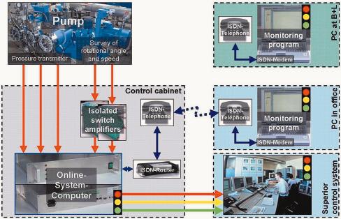
Figure 1 shows the design and principle of operation of the Novalink diagnostic system. A pressure sensor is mounted by way of a rapid-action coupling (can be coupled under pressure during operation!) on the hydraulic chamber of each pump head on the machine. Since the pressure on both sides of the freely vibrating double dia-phragm is the same throughout almost the entire crankshaft rotation, it is thus possible to monitor the pressure curve of the pump both during the compression and expansion phases and during the suction and discharge phases without the sensor coming into contact with the medium.
The rotating speed of the crankshaft (one pulse/revolution) and the rotating angle (several pulses/revolution) of the last driving mechanism are detected by a simple sensor system. The rotating angle variations associated with crankshaft drives can be measured in this manner. The two signals are adapted in the switch cabinet by a disconnector.
These signals (pressure and rotation angle information) are transmitted directly to the online computer of the Novalink CSM system in the switch cabinet. If the process pump is located in a hazardous area, the pressure signals can be transmitted by isolating amplifiers.
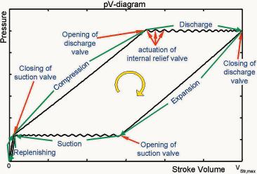
The online computer captures the signals in real time and calculates the pV diagram (pressure-volume diagram, Fig. 2) of each pump head. This pV diagram shows the dynamic response of the working valves, the fluid in the suction and discharge lines and even the behaviour of the membrane positioning control components. Characteristic values such as mean suction and discharge pressures, efficiencies, etc. are computed – likewise in real time – from the pV diagrams and simulation models (pV diagrams of ideal pump heads based on the actual pressure conditions) are created. The online computer continuously monitors selected characteristic values in case they exceed or fall short of predefined limit values (warning and alarm limits). As soon as a limit value is exceeded, the online computer changes from green to yellow for a warning or red for an alarm (traffic light system).
This analysis is conducted for each pump head as well as for the entire pump. The LEDs on the front panel of the computer are switched accordingly, together with the corresponding relays, in order to transfer information to a higher-ranking control system. Furthermore, a record of all data present at the time the limit value was exceeded is stored in the online computer.
Ethernet or telephone
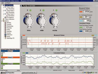
A link can be set up from the PC in the office via the in-house network (Ethernet) or an ISDN telephone line to the online computer, which is likewise connected to the Ethernet or the telephone network via an ISDN modem. Special PC software is then used to dial into the online computer and transfer all current information – pV diagrams, characteristic values, simulation models and traffic light states – from the computer to the PC software. In addition, the data records that were generated when the limit value was exceeded, as well as all other records relating to the actual pump status, are transferred and stored for logging. This data can also be visualised, analysed and compared by the PC software, to enable changes in the pump over a period of time to be investigated (Fig. 3). The PC software moreover supports parameterisation of the online computer and definable fault limits. Remote control of the online system or remote diagnosis of the process pump from the works is thus possible via an ISDN telephone line.
Benefits for applications
In addition to the above-mentioned advantages associated with continuous process pump monitoring, the following benefits are also extremely important:
- Long-term observation permits continuous documentation of the pump status, so that pump faults can be more accurately predicted and maintenance work and schedules planned and optimised in advance.
- Remote diagnosis enables the manufacturer to provide rapid, high-quality service via e-mail and telephone.
- The availability of the process pump is significantly increased and plant downtimes are minimised.
cpp 402
Share:


