According to SIL standard EN 61508, the average probability of failure on demand within a defined proof test interval and the fraction of dangerous undetected failures are the key parameters of protective systems. In order to create gas detection systems that can be classified as, for example, SIL 2, their designers have to pay particular attention to certain numerical limits applicable to these reliability parameters when selecting which subsystems to use, while at the same time ensuring conformance with measurement performance regulations.
Dr. Wolfgang Jessel
Gas detection systems serve as early warning systems to detect potentially hazardous situations in sufficient time for counteraction to be initiated and damage to installations to be either avoided or at least minimised. These gas detection systems are required to conform to Directive 94/9/EC (ATEX 95) not only because they obviously have to feature an explosion-proof design, but above all because they are capable of detecting potentially explosive atmospheres at an early stage and, by allowing counteraction to be taken, can even prevent them from occurring in the first place. As such, the gas detection system forms an integral part of any safety chain and must be additionally tested for suitability in this kind of safety application by a Notified Body (Directive 94/9/EC, Annex II, 1.5.5 “Measuring function for explosion protection“).
Measurement performance standards
The standards upon which this testing is based – EN 50054 ff – will in the foreseeable future be replaced by the 61779-1 to -5 series. According to EN 1127-1, gas detection systems tested in this manner are regarded as active systems for concentration limitation (Section 6.2.2.2), a fundamental explosion protective measure of such high priority that the term primary explosion protection, originally coined some decades ago, is still in common usage today. It is less well known that the use of performance-tested gas detection systems can actually significantly reduce the size of potentially hazardous areas (Ex zones) and, as such, not only simplifies operational processes but ultimately saves money. In the same way, gas detection systems for oxygen measurement also come under the scope of the Directive if they monitor the limitation of oxygen in inertisation processes. The harmonised measurement performance testing standard in this context is EN 50104.
The measurement performance standards are complemented – to the extent that the gas detection instruments contain digital electronics – by EN 50271. Testing in accordance with this standard assesses in particular the software structure and stability, possible special conditions, internal diagnostic facilities plus, of course, the hardware, the interaction between the individual electronic components and the reliability of the functional concept. Functional safety was the main aim when EN 50271 was revised, and it comes as no surprise to learn that some of the requirements of the SIL standard, EN 61508, have already been incorporated into this standard.
Safety Integrity Level
We now need to take a closer look at another aspect of EN 61508 which – assuming certain conditions are met – enables system designers to prove the reliability of a safety-oriented system by means of a numerical evaluation. According to EN 61508, a protective system used to avoid injury to persons or damage to the environment or material assets must meet certain reliability requirements, depending on the extent of the damage that can potentially occur. These requirements are defined on the basis of the so-called Safety Integrity Level (SIL). The concept of reliability is founded on statements of probability such as “How likely is it that a protective system will fail at just the moment it is supposed to be carrying out its safety function?“
Dangerous failures
Safety-oriented systems, therefore, need to be designed such that any failures liable to have a negative effect on functional safety will be recognized, dealt with and reported by suitable self-diagnostic facilities and test routines, and that the system will be restored to a safe condition. Such dangerous detected failures must be remedied immediately. This is moreover in the interests of the operator, as a system in a safe condition, although naturally safe, may not always be ready for operation at the same time. However, even diagnostic systems have their limits. To a certain extent, there will always also be dangerous undetected failures, i.e. failures which result in the failure of the Safety Integrity Function (SIF). The only chance of detecting such failures is to conduct routine system checks. This is the reason why the time between two tests of this kind, the proof test interval TP, plays such an important role in safety analyses. The number of safe failures, i.e. failures which, though they impair the safety function, are detectable as well as failures which have no effect on the safety function, as a proportion of the total number of failures is termed the Safe Failure Fraction (SFF). The SFF must exceed 90 % for SIL 2 systems, i.e. the fraction of dangerous undetected failures must not be greater than 10 %. This alone, however, is not enough. If such dangerous undetected failures are theoretically possible, then the probability of them occurring within the proof test interval TP must also be assessed, i.e. it is necessary to determine how likely it is that the protective system will fail at the precise moment the safety function is needed.
Probability of failure on demand
The statistical parameter which describes dangerous undetected failures and the proof test interval is known as the average probability of failure on demand PFDAVG. It must not exceed defined limits, depending on the required SIL. In the case of systems conforming to SIL 2, for instance, steps must be taken to ensure that the PFDAVG is less than 0.01. The protective system is only allowed to fail once every 100 times the safety function is needed. However, the functional safety and therefore also the average probability of failure on demand PFDAVG relates to the system as a whole, which can be split into the following subsystems: sensor (SE, probability of failure on demand PFDSE), logic solver (LS, probability of failure on demand PFDLS) and final elements (FE, probability of failure on demand PFDFE).
The probability of failure on demand is calculated for the overall system by adding together these three probabilities as follows: PFDAVG = PFDSE + PFDLS + PFDFE. To calculate the PFDSE of a sensor, for example, a very detailed evaluation needs to be performed of every conceivable type of failure as well as its effects on every level, right down to component level. This FMEDA (Failure Modes, Effects and Diagnostic Analysis) is virtually impossible without the assistance of experts specialized in this area. The outcome of the FMEDA is a list of different failure types and their calculated failure rates l (in h-1), on the basis of which the failure rate lDU of dangerous undetected failures, in particular, can be calculated. This kind of failure would occur, for example, if due to an internal failure a 4…20 mA transmitter for gas detection were to indicate a measurement signal of 4 mA (no gas) despite the presence of dangerously high gas concentrations. If this type of rare failure condition arises, it will remain undetected until the next routine test is conducted (proof test interval TP), at which point it will of course be discovered immediately and remedied within a very short time (MTTR or Mean Time To Repair). Statistically speaking, this failure remains undetected for half the proof test interval TP. During this same period, plus the time needed for repair, the system will of course also not be able to perform its safety function. The average probability of failure on demand can accordingly be calculated as follows in this instance:
The approximation is permissible because repairs generally only take a few hours, while the proof test interval covers a period of several months.
Example
The failure rate of dangerous undetected failures is lDU = 10–6 h-1 (i.e. one failure in 106 h or 114 a). If the system is tested annually (every 8,760 h), the following applies:
Dangerous failures detected by diagnostic facilities (failure rate lDD, DD stands for dangerous detected) also have an effect on the PFD, of course, as the safety function is not available during the mean time to repair (MTTR). The MTTR is usually calculated as 8 h, though this naturally assumes sufficient stocks of spare parts and a repair service that is activated without delay. This, and compliance with the required proof test intervals TP, is the responsibility of the safety engineer. If system parts have a redundant design or are subject to voting (e.g. a two-out-of-three decision), the rules which apply deviate from the above formula, e.g. the probability of failure on demand for two-fold redundancy is:
Although the resulting figures are very low (on the basis of the above givens, PFDAVG = 2.6 · 10–5), consideration must realistically also be accorded to failures which influence both subsystems simultaneously, thereby cancelling out the redundancy again; these are known as common cause failures. The proportion of these is expressed by a b-factor which is usually assumed to be 0.05 or 0.1.
In practice, the second term is nearly always larger, even in the case of a low b-factor.
System design
The PFDAVG of the system as a whole, therefore, is determined by the failure rate of dangerous undetected failures lDU, the choice of proof test intervals TP and the architecture (linear, redundant, voting). In the case of the subsystem, the failure rate lDU is determined by conducting an FMEDA, and is usually certified by independent testing institutes and ensured by quality assurance measures. The system designer is consequently able to define the proof test interval and the architecture of the overall system. There are, however, practical limits: companies are not keen for the proof test intervals to be too short, as this can result in more frequent downtime, and redundancies and voting incur considerable costs. It is therefore the system designer’s goal to use subsystems which, if subjected to testing just once every year and provided with no redundant features whatsoever, will fall as far below the maximum permissible PFD as possible.
In the case of a system classified as SIL 2, for example, the designer achieves the aforementioned goal by using a sensor with PFDSE = 0.002 and a logic solver with PFDLS = 0.001, each based on annual proof testing. To ensure the PFDAVG 0.01 that is required for SIL 2, the final elements still to be procured must have a PFDFE of less than 0.007 if they are also to be tested only once a year.
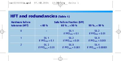
HFT and redundancies
The hardware failure tolerance HFT describes the behaviour of a complex system or subsystem in the event of a failure. With a linear architecture, i.e. in a system without redundancies, the safety function is no longer guaranteed if just one failure (HFT = 0) occurs, while a redundant architecture remains operational even after a failure (HFT = 1 or higher). As can be seen from the above table (refer to EN 61508, Section 7.4.3.1.4), SIL 2 classification can only be achieved with a linear architecture (HFT = 0) if the SFF is greater than 90 %, i.e. the fraction of dangerous undetected failures must be less than 10 %. If, on the other hand, the SFF is a mere 80 %, redundancy (HFT = 1) is essential in order to comply with SIL 2. The functional safety of a subsystem (e.g. a sensor) can therefore only be fully specified by stating the PFD and the respective proof test interval TP, the SFF and the HFT.
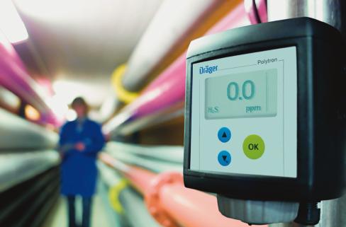
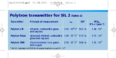
Sensor for SIL 2
When it comes to 4…20 mA transmitters for gas detection, Dräger Safety offers three instruments assessed by an independent institute. As confirmed by the relevant figures in the table for the Polytron transmitters, these sensors are ideally suited for creating a gas detection system classified as SIL 2. For the sake of simplicity, the EN 61508 requirement whereby the complete life cycle of a protective system – especially operation and maintenance aspects – must be taken into consideration has been disregarded in this article. The focus has instead been on familiarising readers with the relevant terms and definitions this standard contains in relation to protective systems.
Hall 7, Booth C45
cpp 436
More information on the products
More on Safety Integrity Level
Share:


