The efficiency of open cooling systems is reduced by the dirt which clogs up conventional filter systems. The subsequent manual work required to clean and replace the filter elements is costly. By contrast, the F450 self-cleaning filter utilises the Bernoulli principle to automatically remove dirt from the cooling system, without interrupting operation.
Dipl.-Ing. Alexander Matosovic
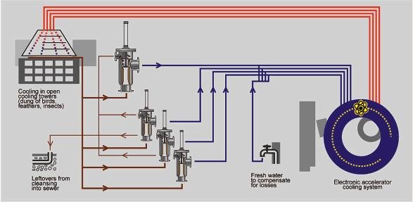
Scientists use “Bessy”, Berlin’s electron synchrotron, to accelerate electrons to almost the speed of light. The researchers use the extremely intensive radiation light from the synchrotron for experiments in the fields of materials research and in particular in pure research. One focal point is x-ray microscopy which is used in several areas of biology and medicine.
Accelerator and storage ring
The synchrotron radiation source releases electrons from a hot cathode in a high vacuum. These electrons are then accelerated by an anode voltage of approximately 10,000 V. The second acceleration stage is a microtron, at the heart of which is a small, high-frequency linear accelerator. The electrons are held in the magnetic field of the microtron on tracks of increasing circumference where a final energy of 50 million eV is achieved. The particles then enter a ring shaped vacuum chamber which has a circumference of 96 m. The electrons are held by powerful magnets on a track inside the vacuum tube and are again accelerated by alternating magnetic fields.
This acceleration cycle is repeated at a rate of 10 Hz. In other words, around 10 billion electrons are accelerated to final energy ten times per second. The actual storage ring has a circumference of 240 m. The synchrotron radiation leaves the storage ring through tubes which measure up to 40 m in length and makes its way via mirrors to the individual experimenting stations.
Solution to the cooling problem
Though the electron accelerator installation is highly complex, its problem concerning the open cooling tower system was straight-forward enough. Even though the cooling towers were installed in a specially constructed recess in the building, the area was continually being heavily contaminated by its environment. Every operator of a cooling tower system knows the problems caused by leaves, insects, pollen, feathers, bird droppings and other forms of contamination which can be brought into the system either in the air or by animals. Likewise the large number of insects was also a recurring problem for the cooling system, resulting in blockage of the single filter. The manual cleaning operations, the amount of time that this takes and the risk of cooling circuit problems are inconsistent with the high-tech environment of the installation.
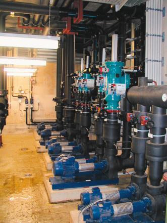
Thanks to the F450 automatic self-cleaning filter, the cooling water system of the electron storage ring can be effectively protected. This filter cleans without any mechanical intervention being required and without interrupting the continuous filtration process.
Theoretical physics in action
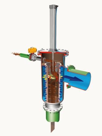
The geometry and location of the flanges in the F450 filter ensure that dirt is deposited along a defined path, from the end of the filter screen to the inlet: The flow speed inside the filter decreases and the static pressure at the filter inlet increases until the differential pressure switch initiates the automatic flushing process, without actually interrupting filtration at all.
The self-cleaning process is effected by utilising the increase in flow speed and the associated pressure ratios at the screen. According to Bernoulli’s law, the sum of the dynamic and static pressures in flowing liquids is constant. This means that when the flow speed decreases, static pressure rises, and when speed increases, static pres-sure drops. The filter utilises this law. The filter, which the medium approaches axially, filters from the inside out, with the cleaned medium exiting the filter via a radially positioned outlet flange. As a result of the pressure ratios created by the geometry and the locations of the flanges, dirt deposits on the inside of the screen follow a defined path. Dirt is deposited initially at the end of the screen insert and then, as operation continues, is gradually deposited in a path that extends right up to the inlet. Because of the geometry and the resulting high flow speed at the inlet, the pressure inside the screen is initially lower than outside. As more and more dirt is deposited on the screen from the top down, the flow speed continues to drop. In accordance with Bernoulli’s law, as flow speed drops, the pres-sure in the screen increases and once approximately one third of the screen has been covered, the pressure inside exceeds the pressure outside.
Two-phase flushing process
Once a pressure differential of 0.11 bar has been reached, a differential pressure switch will initiate the self-cleaning flushing process, which is done in two phases. First, the flushing valve is opened against atmospheric pressure and the flushing flow is released. This lifts the easy to remove coarse particles from the filter surface. These then flow in the direction of the dirt outlet and exit the filter via the flushing valve. This action, however, does not produce any reverse flow effect at the filter surface. The first flushing phase lasts for around 5 s. The flushing quantity is adapted to the operating conditions by adjusting the cross section of the flushing valve.
Phase two also uses the Bernoulli principle. Driven by a compressed-air cylinder a specially shaped flushing disc is led past the inner surface of the screen. The flushing disc reduces the flow cross section inside the filter, which causes a partial increase in speed between the disc and the filter insert. The static pressure in this area is drastically reduced by the increase in speed. The resulting localised pressure drop, together with the cavitation occurring downstream of the flushing disc, causes the deposits to be sucked off the entire inside of the filter insert. The deposits are released to the contamination side through the gaps and are discharged via the pressure drop at the open flushing valve. So as not to interrupt the flow of medium entirely, flushing disc and piston are designed so that only around two thirds of the screen is being passed over. The area that is not being passed over is cleaned by the reverse flow effect caused by the drop in static pressure.
Advantages of installing the filter
The filter can continually treat process water in any installation location, without any interruption in operation. The filter can also be installed either lying down or inline at 45° angles – a particular advantage in pipeline construction, especially when working with nominal widths of over 500 mm. The filter can be made from stainless steel, coated steel, GRP, PVC or PP/PE and is therefore also resistant to any aggressive components in the medium. Filter size is not dependent on filter mesh size and is only determined by throughput. With filter mesh sizes of 150 µm and upwards, this filter can tackle water flow rates of more than 6000 m3/h. The simple construction enables it to be installed in virtually any existing pipeline system. Thanks to the minimal maintenance costs and lightweight design, it is also possible to install it in places that are difficult to access.
A control unit is connected to the integral differential pressure measuring system, enabling direct transmission of recorded data. To optimize processes, it is also possible to pre-set flushing intervals. Explosion protection and Atex regulations are met. A 220 V power supply and a compressed-air supply of 4 to 6 bar are required to operate the filter.
cpp 432
Share:


