Jet cleaners are often used for intensive cleaning of tanks, vessels and other closed plant components. Devices operating at pressures from 3 to 50 bar, in some cases also up to 70 bar, are driven either by an external electric or pneumatic motor or by means of the cleansing agent itself. The CIPMon SC sensors, which are mounted onto the outside of the vessel, assure hygienic jet cleaner monitoring.
Thomas Meierkordt
The required cleansing agent pres-sure and throughput, and a sufficient rotation speed of the nozzle system, are essential preconditions for smooth operation of a jet cleaner. In addition to the choice of the most appropriate cleansing agent, it is these operational parameters that determine the cleaning effect. Once they have been optimised and veri-fied, these physical parameters must not be allowed to be altered by unauthorised persons. Nevertheless, malfunctions in the process cannot be completely avoided. They can be caused, for example, by pump failures (reduced conveying capacity without standstill) or by a cleansing agent leakage in the supply conduit.
Sensors are generally used to monitor the operation of jet cleaners such as the AWH CIPMon PC1. The results are often unreliable and suggest that the cleaning process is functioning efficiently when this is not the case. Hygienic problems in the tank to be cleaned are inevitable. Furthermore, for technical reasons, the sensor requires an additional connection piece on the vessel that needs to be cleaned as well.
No additional flanges
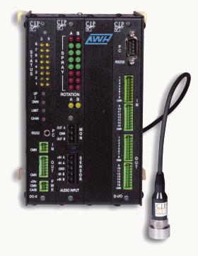
The sensors in the CIPMon SC series now permit operation of a jet cleaner to be monitored externally without any additional flanges. Hygienic problems created by the sensor are hence excluded. In the case of jacketed tanks, a point in the downpipe area (flange or surrounding) normally provides direct access to the vessel wall. During assembly, a sensor support is glued or welded onto the outside of the vessel (Figure 1). The assembly process is completed in a few minutes, thus facilitating initial results in a very short time. The distance between the sensor and the evaluation unit is generally only a few metres, although it can occasionally be as much as 100 m or more. The evaluation unit (supply voltage: 24 V) is installed in a local switch cabinet. The switch points are transferred to a PLC in the usual way or can simply be read on the front. The optional software (runs on any standard PC) permits various evaluations beyond the scope of normal operation (nozzle monitoring) as well as archiving of the operational data. CIPMon SC sensors record the oscillation or vibration produced by the cleansing agent jet on the vessel wall. The measured values are compared with ratios for the rotation speed and the jet impact, allowing a wide range of evaluations.
Oscillation signals recorded
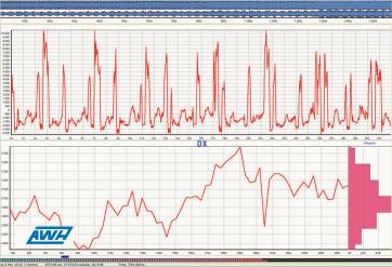
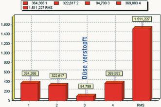
During the cleaning cycle, the moving cleansing agent jet hits the inner wall of the vessel and thus generates oscillation signals of varying strength in the sensor, which is fixed-mounted on the outside. The resulting, evaluated relative impact signal is shown in Figure 2 together with its variance. For monitoring the jet cleaner, the minimum and maximum DX values are taken into consideration as typical characteristics and entered as limit values. Values below or above the relative impact signal lead to an error message. Clogging of one or more nozzles can be the cause of disturbances. In this case, the operational status of the nozzles can be compared with historical nozzle status charts stored in the software. Jet cleaner operating problems can thus be easily identified. In Figure 3, one of the four jet cleaner nozzles is clogged. One considerable advantage of the CIPMon SC and the monitoring software is that the user is supplied with information about the jet cleaner status almost instantly without having to open the vessel or undertake any assembly work.
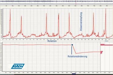
The rotation speed of a medium-driven jet cleaner is easily altered if the pressure or volume flow is reduced. As a result, the number of rotations required for a complete cycle is not reached within the specified time. Figure 4 shows how a change in the nozzle behaviour leads to a decrease in rotation speed. By activating the lower or upper control limit values, any deviations from the specified speed are detected immediately and an alarm is tripped. In the case of devices driven by an electric or pneumatic motor, in other words externally, the source of a disturbance is usually the supplied energy. Once again, failures can be reliably detected by monitoring the rotation speed of the jet cleaner. Leakages in the pneumatic supply system or malfunctions in the motor that result in a reduction in rotation speed are signalled precisely.
Objective evaluation aid
The CIPMon SC represents an objective evaluation aid for developing and optimising jet cleaners. It records the impact of a jet cleaner as a function of the medium pres-sure and the nozzle length. The jet pressure and the throughput of the cleansing agent rise as this pressure increases. The DX curve (impact) has a downward slope again after an inflection point. This reduced impact describes the nozzle design, geometry and various other parameters. An increase in cleansing agent throughput improves the cleaning effect and is a significant cause of higher pressures. The nozzles can thus be optimised for any application. This clearly illustrates why the range of a jet cleaner should not be the only parameter to be taken into consideration. With a thin jet that provides a broad range, only a small amount of cleansing medium will reach the vessel wall. Although the cleaning effect is good, fine lines will appear on the cleaned surface. They can be removed by applying a broader jet that is adjusted to the correct distance. This arrangement inevitably leads to a higher cleansing agent consumption. As a general rule, an integral examination of the pressure, nozzle design, cleansing agent quantity and type and process control is vital for optimal cleaning results.
Configurations
The CIPMon SC sensors are available in several different configurations. The simplest type is a single-channel version in a narrow housing. Figure 1 shows an extended version with a spare slot for an additional mod-ule, two measuring points and an interface card for connection to the control room. A further module for two measuring points can optionally be integrated instead of the interface card. Another application of the CIPMon-Sc sensors, which are currently on trial, is monitoring of surge cleaners (Spinner series). The rotation speed of these devices is many times that of a slowly rotating jet cleaner (5 to 40 rpm). Insufficiently filtered CIP media or particulate matter in the ball bearings are potential sources of disturbances in surge cleaners operation. Particulate matter can penetrate into the ball bearings during the production process of the cleaning device. Both malfunctions can be reliably detected by monitoring the rotation speed with the CIPMon SC, a fact that is of great significance for CIP processes requiring validation.
Hall 9.0, Booth F35
cpp 435

More on the products
Druckgeräte Online
Achema 2006
Share:


